background image


7

/

14


Supported functions: 

(1)


Controlling GRBL-based CNC-machine via console commands, buttons on form, numpad.   

(2)


Monitoring CNC-machine state. 

(3)


Load, edit, save and send G-code files to CNC-machine. 

(4)


Visualizing G-code files.


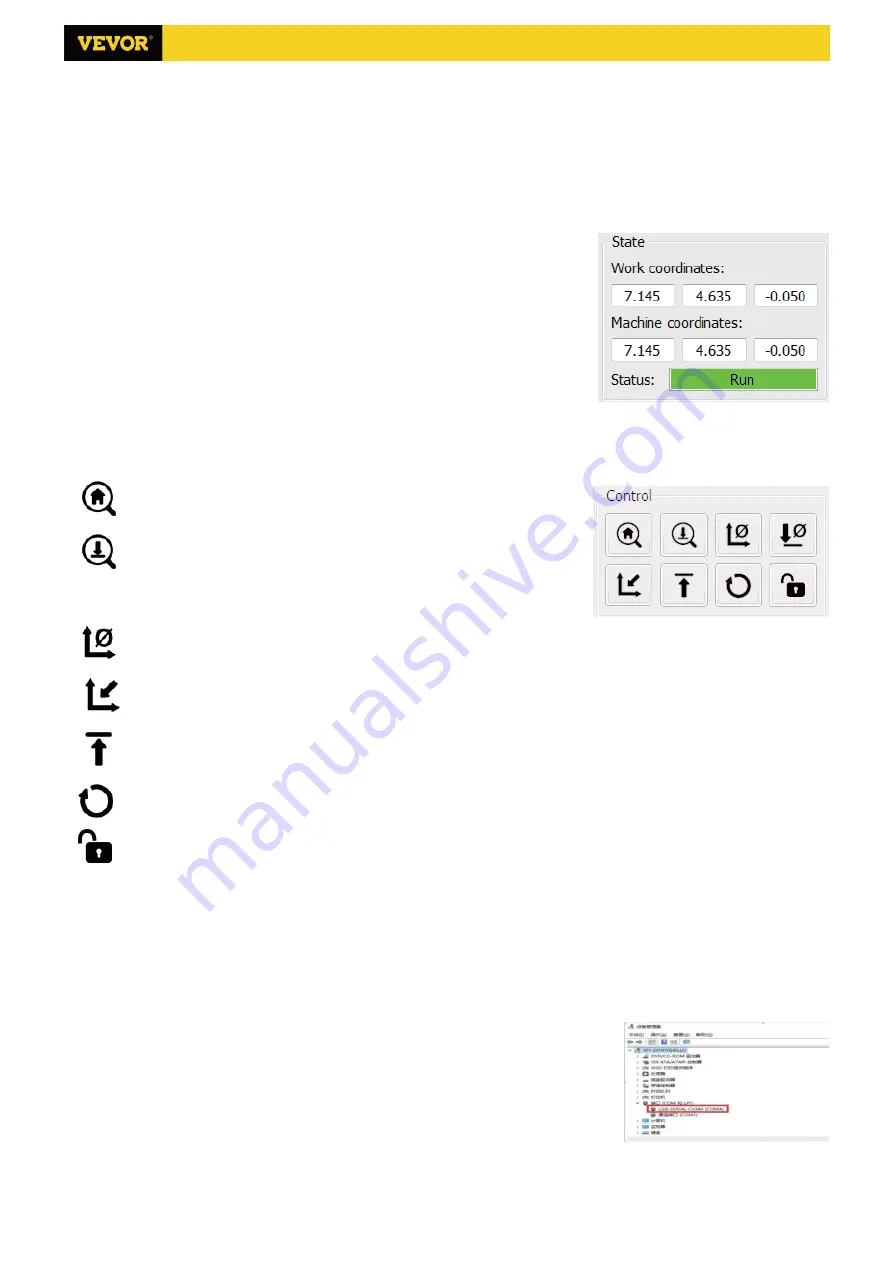
4.1 States 

    Work coordinates:   
        Represents current X, Y & Z local coordinates of the CNC. 
    Machine coordinates:   
        Represents current X, Y & Z absolute machine coordinates. 
    One of following CNC status:           
      Idle - waiting for a G-code command Running - running a G-code command         
      Home - homing cycle is executing 
      Check - G-code command check mode is turned on   
      Hold - paused by a "!" command, need to be restarted by a "~" command   
      Alarm - CNC doesn't know where it is and blocks all G-code commands   
 

4.2 Control 
 

Home button 

Starts the homing cycle procedure with "$H" command


Z-probe 

Starts  the  zero  Z-axis  search  procedure  using  the  command  specified  in  the 

settings 

("Z-probe  commands" 

box). 

Example 

command:G91G21; 

G38.2Z-30F100; G0Z1; G38.2Z-1F10 
 

Zero X/Y 

Zeroes the "X" and "Y" coordinates in the local coordinate system. Also retains an local system offset ("G92") for later use.


Restore X/Y/Z 

Restores local system coordinates with "G92" command. 


Safe Z 

Moves  tool  by  "Z"-axis  to  safe  position.  Position  coordinate  can  be  specified  in  the  "Safe  Z"  setting.  Position  must  be 
specified in machine coordinates. 

Reset 

Resets CNC with "CTRL+X" command 
 

Unlock   

Unlocks CNC with "$X" command. 


4.3 Software using steps 

(1).


Install the driver


    For the first time use, please connect the device to the computer via USB cable, and click the CH340-Driver.exe file in 
the driver folder to install the driver. Under normal circumstances, the Win10 system will automatically identify and 
install the driver. For Win7 and Win8 systems, please install it manually. 
 

(2)


Set the port and connection


    After installing the driver, open the device manager of the computer and click on 
the port option to see the content inside the red box on the screen shown in the 
figure below (the port information is in brackets).


    Remember the port information queried above, switch to the 

Candle

 software 

interface and click the "Settings" option in the upper left corner. Selecting the setting 
will pop up the setting window. Under "Connection", select the port name you queried, select the baud rate 115200, 
and then click the "ok" to finish the setting. 

S3018 Pro Ver 2.3

Содержание S3018 Pro

Страница 1: ...ncy Shutdown steps first cut off the power then pull out the USB cable Precautions 1 All parts description just for illustrative purpose If there is any difference please refer to the actual part shap...

Страница 2: ...e 4P 3 18 Hand knob X Y 8 18mm 2 C6 Spindle motor ire 2P 1 19 Hand knob Z 5 18mm 1 20 Inner he agon scre M5 16 12 21 Inner he agon scre M5 20 20 C8 USB cable 1 22 Inner he agon scre M3 14 4 C9 Po er s...

Страница 3: ...M4 5 1PCS Set Screw for knob 20 M5 16 12PCS Screw 05 Connecting plate back 1PCS 13 Stepper motor 1PCS 22 M3 14 4PCS Screw 18 8 18mm 1PCS Hand knob Y 04 Connecting plate font 1PCS D i r e c t i o n o...

Страница 4: ...Screw 4PCS 13 Stepper motor 1PCS 23 M3 18 screw 4PCS D irection of connecting w ire 06 Connecting plate left 1PCS 25 Trapezoidal nut M5 20 6PCS 21 M5 20 Screw 10PCS 18 Hand knob X 8 18mm 1PCS 27 M4 5...

Страница 5: ...Step 5 14 The plastic column must be assembled between the control board and the aluminum parts C4 M5 10 4PCS Ship nut C1 Control board 1PCS C2 Column 4PCS C3 M5 10 4PCS Screw S3018 Pro Ver 2 3...

Страница 6: ...lease lay the materials to be engraved flat under the laser The recommended distance from laser outlet to materials is 3 10cm Out of range may be out of focus Turn on the weak light Rotate the focusin...

Страница 7: ...later use Restore X Y Z Restores local system coordinates with G92 command Safe Z Moves tool by Z axis to safe position Position coordinate can be specified in the Safe Z setting Position must be spec...

Страница 8: ...nterface click Open to select a G code file that has been made to import the file After importing the middle of the interface will display a visual graph composed of tool paths the position of the pen...

Страница 9: ...ance of one sheet of paper for engraving and then return the X Y and Z axes to zero please use a flat bottom sharp knife when engraving and use a cylindrical milling cutter when machining planes slots...

Страница 10: ...ion is the operation of controlling the device through software after the device is connected to the computer 1 Connect the device to the computer with a USB cable 2 Place the material to be engraved...

Страница 11: ...hoose low power Q Which formats are supported Support all formats of images support GCODE NC files If you want to engrave DXF file please use the VigoWorks software Visit our website www VevorEngraver...

Страница 12: ...ess to open the spindle corresponding to SPN gray on the screen press again to close the spindle the corresponding SPN on the screen returns to normal Long press to enter changing spindle speed page A...

Страница 13: ...is a dot in the upper left corner of the main page The RED dot indicates that VIGO STK hotspot is active and the GREEN dot indicates that the controller has connected to Local WiFi The web management...

Страница 14: ...dows and run it Click the button Connect After the software connected the machine successfully click Settings On the settings window Click Restore Factory button then reboot the machine Method 2 Run C...

Отзывы: