Rev. 5/8/2019
ZLTT MANUAL
Copyright 2019 Vestil Manufacturing Co.
Page 11 of 15
•
Releasing the DOWN button during operation causes motion to stop.
The tabletop maintains position until you press a control button.
•
A lower limit switch stops the motor when the tabletop is completely
lowered.
B. TILT UP and TILT DOWN functions
1. Tilt the tabletop by pressing the TILT UP button.
•
The motor turns and rotates the gear pump. While the pump rotates, oil
is drawn out of the reservoir.
•
Oil passes through the suction filter and enters the pump.
•
The pump propels oil through the check valve and towards the lift
cylinders.
•
Releasing the button immediately halts the tabletop.
•
A limit switch automatically turns off the motor when the tabletop
reaches its maximum height.
2. Un-tilt the tabletop by pressing the TILT DOWN button.
•
The lowering valve opens and bypasses the check valve. Oil in the cylinder flows to the reservoir. Oil flow
is regulated by the pressure compensated flow control valve. By regulating the volume of oil that can flow
through the spool, the tabletop un-tilts at a constant speed.
•
Releasing the TILT DOWN button during operation causes motion to stop. The tabletop maintains
position until you press a control button.
•
A lower limit switch stops the motor when the tabletop is completely un-tilted.
Hydraulic system issues and solutions
on p. 3 as necessary to determine component location.
A. If the table slowly lowers or un-tilts
without pressing either of the necessary control buttons, then the
corresponding lowering cartridge valve needs to be cleaned. Remove, inspect, and clean the lowering cartridge
valve. If the tabletop
un-tilts
on its own, valve LLB must be removed and cleaned. If the table
lowers
on its own,
remove and clean valve LLA.
1. Press the TILT DOWN button. Then, press the LOWER button until the tabletop returns to home position.
2. Disconnect all electrical power to the equipment.
3. Unload the table.
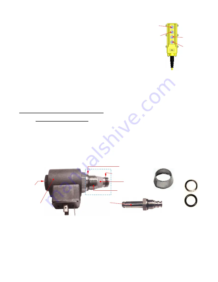
4. Remove the valve retaining nut that fastens the solenoid coil to the valve stem. Then, unscrew the valve
from the manifold (not shown).
NOTE
: The end of the valve inside the dashed lines winds into the manifold. It is not visible until the
valve is unscrewed from the manifold.
5. Inspect the outside of the valve and the valve cavity in the manifold (not shown) for debris. Replace the
valve if the valve stem is bent.
6. Inspect the O-ring and the outer seal for cuts, tears etc.
7. Remove debris from the valve:
a. Use a small screwdriver to press on the end of the valve. Insert the screwdriver into the valve as shown
on the following page. A poppet inside the valve is held closed by spring tension. If the poppet is
unaffected by debris, it moves approximately
1
/
16
” when pressed. If the poppet cannot move when
pressed, the valve might be damaged. Blow compressed air through the valve while pressing the
poppet open. Mineral-spirits or kerosene can be used to flush debris out of the valve.
Handheld Controller and
Control Buttons
Valve
O-ring (round)
Outer seal (2 parts)
Screen
Valve retaining
hex nut
Screen
Outer seal
(flat)
O-ring
(round)
Valve threads that
wind into manifold
Solenoid coil
Valve assembly
Valve stem
TILT
UP
TILT
DOWN
LIFT
LOWER


