Rev. 5/8/2019
ZLTT MANUAL
Copyright 2019 Vestil Manufacturing Co.
Page 10 of 15
Loading the Table
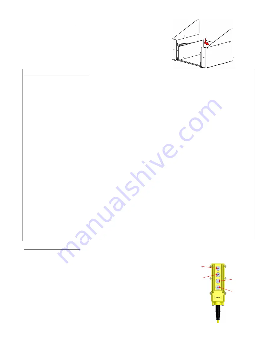
ZLTT-series tables include a backstop feature to retain loads
while the tabletop is tilted. The open side of the table provides a
tapered edge for pallet trucks to access the table interior. The
backstop will be lower than the open side of the table when it is
tilted so the load must rest against the backstop when it is applied
to the table. Otherwise, as the table tilts the load will slide. The
load should also be centered against the backstop. The load
center should be no more than 36 inches above the tabletop.
Sequence of Operation
Powered lift and tilt functions are provided by an electric-hydraulic power unit (EHPU). The EHPU uses an
electric motor coupled to a gear-type hydraulic pump to pressurize the hydraulic system. Hydraulic pressure
allows the cylinders to extend. Cylinder extension lifts and tilts the tabletop. Control components are housed
inside a manifold bolted onto the gear pump. All hydraulic components are rated for 3,000 psi working pressure.
Standard units utilize a 4-button, constant pressure (dead man), push-button controller. Pressing the LIFT
button extends the lift cylinder and raises the tabletop. The tabletop remains horizontal. Press the TILT UP button
to tilt the tabletop up to a maximum angle of 45°. The table moves only as long as a button is pressed. The
tabletop stops as soon as the button is released and maintains position until a button is pressed.
Notable parts of the power unit include:
•
Electric motor: Used to power the hydraulic system. The motor is either single-phase AC or three-phase AC
as selected by the customer. Regardless of phase, every motor is dual-voltage capable.
•
Gear pump: The pump shaft is coupled directly to the shaft of the electric motor. Several displacements are
available to match the horsepower of the motor selected.
•
Check valve: Prevents backflow of fluid through the pump. This allows the tabletop to maintain
position/configuration when the handheld controller is not in use.
•
Pressure relief valve: This valve opens a path for fluid to flow back to the reservoir if fluid pressure exceeds
3,000psi. The relief valve is a safety feature designed to prevent damage to the hydraulic system that would
otherwise be caused by excessive pressure.
•
Lowering solenoid valve: An electrically-operated cartridge valve with an integral screen. The screen prevents
contaminants from entering the valve.
•
Pressure compensated flow control spool: The spool determines the cylinder retraction speed and thereby
fixes the lowering speed of the tabletop. The spool is located beneath the lowering valve. This component
allows the tabletop to descend at a constant rate regardless of the weight applied to it.
•
Hydraulic cylinders: Extend and retract to change the configuration of the tabletop. Each cylinder includes a
bleeder valve located at the top end. The bleeder allows air to be removed from the hydraulic system.
•
Velocity fuse: A safety device installed in the hose port of each cylinder. The fuse closes automatically if a
sudden, significant drop in hydraulic pressure occurs. A closed fuse traps oil inside the cylinder which
prevents the cylinder from retracting further. Consequently, the tabletop remains stationary until system
pressure is reestablished.
•
Hydraulic fluid: HO150 hydraulic fluid. Only use anti-wear hydraulic fluid with a viscosity grade of 150 SUS at
100°F (ISO 32 @ 40°C) like AW-32 or Dexron transmission fluid.
Operating the Table
A. LIFT and LOWER functions
1. Raise the tabletop by pressing the LIFT button.
•
The motor turns and rotates the gear pump. While the pump rotates, oil
is drawn out of the reservoir.
•
Oil passes through the suction filter and enters the pump.
•
The pump propels oil through the check valve and towards the lift
cylinders.
•
Releasing the button immediately halts the tabletop.
•
A limit switch automatically turns off the motor when the tabletop
reaches its maximum height.
2. Lower the tabletop by pressing the LOWER button.
•
The lowering valve opens and bypasses the check valve. Oil in the
cylinder flows to the reservoir. Oil flow is regulated by the pressure
compensated flow control valve. By regulating the volume of oil that
can flow through the spool, the speed at which the tabletop lowers is
constant.
Load firmly
contacts
backstop
Handheld Controller and
Control Buttons
TILT
UP
TILT
DOWN
LIFT
LOWER


