background image

Rev. 9/25/2017 


  HDC-450, MANUAL 

Copyright 2017 Vestil Manufacturing Corp.                                                                                     Page 21 of 26          


Using the Battery Charger (HDC-DC units only):


Batteries contain sulfuric acid and produce explosive gases. A battery explosion could result in loss 

of eyesight and/or serious burns. Always have plenty of fresh water and soap nearby. 

  DO NOT smoke near the battery or expose the battery to a spark or flame. 

  ONLY charge batteries 

in 

dry, well-ventilated


locations. 

  DO NOT lay metallic items, like tools, on top of a

 b

attery. 

  NEVER touch both terminals simultaneously! Remove personal jewelry items such as rings and watches. 

  Operating the battery with low voltage can cause premature motor contact failure. 

  The charger is equipped with an external ground wire (small green wire). During installation the charger must be 

grounded to the equipment. Be sure this wire is always connected to the chassis, frame, or other metallic surface 
considered to be ground. 

  Remove accumulated deposits from the terminals. Confirm that all battery connections are sound. 

  Replace defective electrical cords and wires immediately. 

  DO NOT use the charger if the flanged inlet is damaged. 

  DO NOT connect the charger to a damaged extension cord. 


DC-powered drum carriers are equipped with an onboard battery charger with a flanged electrical inlet. The inlet 

projects through the cover/housing of the power unit. The user must provide a 3-prong charging cord appropriate for line 
and motor voltages. The charger is current limited and will not exceed its rated output even if loads are placed on the 
battery while it is charging. The charger fuse will blow if it is connected in reverse polarity. To charge the battery: 

1.) Plug an extension cord into the flanged inlet

. Plug the other end of the cord into 

an 115V, 60 Hz receptacle (or 

receptacle that matches the unit’s voltage rating)

.

 Use a short, thick extension cord to minimize voltage drop (no smaller 

than 18ga. or longer than 50 ft.). 

2.) The charge LED indicates the status of charge current flowing to the battery. 

 Red LED only: charger is providing full output to the battery. 

 Red and green LED's: charger is "topping off" 

the 

battery. 

 Green LED only: unit is providing a "float" (maintenance) charge. 

 DO NOT leave the charger on for long periods after the battery is fully charged. 

3.) Unplug the charger before using the unit to avoid damaging cords, receptacles, etc. 


CHARGER TROUBLESHOOTING

: If the charger does not work:


1)  Make sure all battery connections are sound. 
2)  Confirm that the AC power source (e.g. wall socket) is supplying power. 
3)  Examine the fuse (see diagrams on pages 13-14 (DC-powered) or 16-17(AC-powered)). Replace only with a fuse 

having the same rating as the original fuse. 

4)  It will take time before current begins to flow through a highly sulfated battery. 


Содержание HDC-450 Series

Страница 1: ...DC 450 84 Exploded Parts Diagram and Bill of Materials 7 8 HDC 450 96 Exploded Parts Diagram and Bill of Materials 8 9 Hydraulic System Foot Pump Standard Units Operation Purging Air from the Pump Pur...

Страница 2: ...he drum handler The product is labeled with its capacity see Label 287 in Labeling diagram on p 25 Capacity is reduced to 500 pounds whenever a drum is half full or less Inspect the product as directe...

Страница 3: ...1 16 493 16 547 8 453 4 1091 4 60 773 8 800 lb 364 kg 533 lb 243 kg HDC 450 72 91 11 16 41 11 16 49 3 16 54 7 8 45 3 4 109 1 4 72 92 1 2 800 lb 364 kg 535 lb 243 kg HDC 450 84 110 9 16 4511 16 533 16...

Страница 4: ...Rev 9 25 2017 HDC 450 MANUAL Copyright 2017 Vestil Manufacturing Corp Page 4 of 26 HDC 450 60 Exploded Parts Diagram Bill of Materials on p 5...

Страница 5: ...1 33 16 132 216 Caster wheel GFN 8 2 W 2 17 11129 Hex bolt gr A zinc finish 3 8 16x8 2 34 15 023 001 Reservoir non structural 1 HDC 450 60 Bill of Materials Exploded Parts Diagram on p 4 HDC 450 72 Bi...

Страница 6: ...Rev 9 25 2017 HDC 450 MANUAL Copyright 2017 Vestil Manufacturing Corp Page 6 of 26 HDC 450 72 Exploded Parts Diagram Bill of Materials on p 5...

Страница 7: ...Rev 9 25 2017 HDC 450 MANUAL Copyright 2017 Vestil Manufacturing Corp Page 7 of 26 HDC 450 84 Exploded Parts Diagram Bill of Materials on p 8...

Страница 8: ...025 023 Handle grip 11 8 I D red 2 16 09 112 029 Pin clevis 2 32 09 516 004 001 Subassembly gear train pull chain 1 33 15 023 001 Reservoir 1 HDC 450 96 Exploded Parts Diagram Exploded Parts Diagram o...

Страница 9: ...Rev 9 25 2017 HDC 450 MANUAL Copyright 2017 Vestil Manufacturing Corp Page 9 of 26 HDC 450 96 Exploded Parts Diagram Bill of Materials on p 8...

Страница 10: ...s at a controlled rate Do not increase the pressure relief setting more than necessary i e be sure that you do not exceed the pressure rating of the components in the hydraulic system Purging Air from...

Страница 11: ...n the rear and the other is located on the right side of the pump body Including 2 pressure ports and 2 intake return ports allows the circuit configuration to be adapted to varied applications The un...

Страница 12: ...sure compensated 1 0 gal 1 7 99 114 001 Washer beveled spring washer 8 8 99 146 008 Spring relief 1 9 99 653 005 Assembly release valve packing 1 9 1 99 031 022 Accessory hydraulic relief valve pin se...

Страница 13: ...ly OR I can pump the pedal but the arm does not move g Pump is air locked h Debris on seat of inlet check valve i Pressure setting of relief valve needs adjustment j Debris on seat of relief valve g R...

Страница 14: ...her 1 9 15 533 013 Cable battery 23 black 1 10 15 533 014 Cable battery 23 red 1 11 23305 33688 33008 3 8 16 x 1 utility grade bolt 3 8 high collar lock washer 3 8 flat washer 2 2 2 12 99 135 011 4 12...

Страница 15: ...Description Qty 31 568 015 BN70 O ring 1 32 568 011 BN70 O ring 1 33 99 153 058 Valve cartridge normally closed 1 34 99 034 010 Coil with weather tite plug 1 35 99 153 006 Valve pressure relief 1 36 5...

Страница 16: ...Rev 9 25 2017 HDC 450 MANUAL Copyright 2017 Vestil Manufacturing Corp Page 16 of 26 12VDC modular power unit layout part 2 of 2 12VDC modular power unit layout part 1 of 2...

Страница 17: ...688 33008 3 8 16 x 1 utility grade bolt 3 8 high collar lock washer 3 8 flat washer 2 2 2 12 01 627 010 Manifold see FIG 6C 1 13 01 143 906 Pump 1 14 HS52 Worm gear hose clamp 1 15 091802JY Fiberglass...

Страница 18: ...enclosure plate 1 9 C500 3 8 1 2 knockout Romex 2 screw NM clamp connector 4 10 01 127 010 LHL standard manifold 3 boss 1 11 6801 06 06 NOW 3 8 16 x 1 utility grade bolt 2 12 99 153 011 Check valve 1...

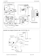
Страница 19: ...Rev 9 25 2017 HDC 450 MANUAL Copyright 2017 Vestil Manufacturing Corp Page 19 of 26 Hydraulic circuit diagram Powered units 01 127 010 Rev C 115VAC modular power unit layout Cylinder...

Страница 20: ...might occasionally need to be cleaned see Troubleshooting on p 24 25 Before working on any part of the hydraulic system always lower the carriage 1 Remove the cover from the power unit 2 Identify the...

Страница 21: ...d electrical inlet The inlet projects through the cover housing of the power unit The user must provide a 3 prong charging cord appropriate for line and motor voltages The charger is current limited a...

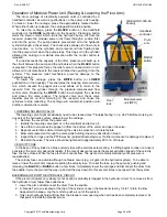
Страница 22: ...Hinged doors Gear handle Saddle in horizontal position 4 Lift the drum just a few inches above the ground using either the foot pump standard units or modular power unit HDC DC and HDC AC options Ins...

Страница 23: ...nections 4 Frame elements inspect the legs vertical members and braces for cracked welds bends etc 5 Saddle drum retainer and pivot arm visually examine each element for damage Pay particular attentio...

Страница 24: ...verloaded o Inoperative pump k Lower the carriage Remove the lowering solenoid valve and clean Refer to p 20 l Correct as appropriate See also 2 f h m See 1 b n See 2 e o See 2 j 4 Motor labors or is...

Страница 25: ...el that is damaged and or not easily readable Numbers below label images in the diagram correspond to the identification number of each label C Label 287 applied to upright frame member A Label 220 ap...

Страница 26: ...e warranty covers defects in the following original dynamic components motors hydraulic pumps electronic controllers switches and cylinders It also covers defects in original parts that wear under nor...

Отзывы: