background image

Rev. 9/25/2017 


  HDC-450, MANUAL 

Copyright 2017 Vestil Manufacturing Corp.                                                                                     Page 5 of 26          


Item 

Part no. 

Description 

Qty.  Item 

Part no. 

Description 

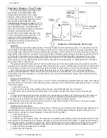
Qty. 

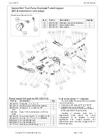
1 09-514-043  Weldment, base with mast 

18 

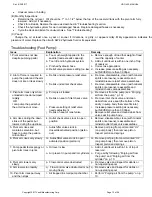
36106 

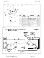
Hex nut, gr. A, zinc plated, 

3

/

8

”-16 2 

2 09-514-094  Weldment, pivot arm 

19 

16-145-031  Bolt with grease jerk, 

1

/

2

”-13 x 3

1

/

2” 

3 09-538-005  Drum carriage/saddle assembly  

20 

33008 

Flat washer, low carbon, USS, 
zinc plated, 

3

/

8

” 

09-516-004-

005 

Subassembly, gear train, hand crank  1 21 

09-516-004-

A3 

Bushing, bronze, 37mm long, 
20mm shaft 

5 09-024-002  Cover, tube cap 

22 

11103 

Hex bolt, gr. A, zinc plated, 

3

/

8

”-16 

3

/

4

” 

6 33-112-034  Clevis pin, zinc plated, 

3

/

4

” x 3

3

/

4

” 

23 

09-516-079  Bracket, weldment, small door 

45286 

#11 hitch pin clip, 

1

/

8

” x 2

5

/

8

” 3 

24 

38623 

HHCS, metric, zinc plate, 8.8 M8 x 
1.25 x 60mm 

8 09-016-087  Bracket, spacer, drum saddle 

25 

40163 

M8-1.25 Nylock nut 

9 09-516-006  Weldment assembly, hinged door 

26  09-002-004-A 

3

/

16

” coil chain, 33” long 

10 37030 

1

/

2

”-13 Nylon insert lock nut 

27 

01-016-018  Pump, manual base plate 

11 99-640-005  Hydraulic foot pump, autoshifter 

28 

11105 

Hex bolt, gr. A, zinc plated, 

3

/

8

”-16 

x 1” 

12 16-132-350  Floor lock 

29 

99-021-904-

001 

Cylinder, hydraulic, 1

1

/

2

”x18” 1 

13 

11119 

Hex bolt, gr. A, zinc finish, 

3

/

8

”-16x4” 

30 

16-132-021  Swivel caster, PU-5/2-S 

14 33622 

Split lock washer, carbon steel, 
medium zinc finish, 

3

/

8

” 

2 31 99-612-001 

Pin, caster receiver nut and bolt 
combo. 

15 37024 

Nylon insert lock nut, gr. 2, zinc 
finish, 

3

/

8

”-16 

5 32 13-025-023 

Handle 

grip, 

1

1

/

8

”I.D. red 

16 14-025-001  Handle, crank, 

5

/

8

” square end 

33 

16-132-216  Caster, wheel, GFN-8/2-W 

17 

11129 

Hex bolt, gr. A, zinc finish, 

3

/

8

”-16x8” 

2 34 15-023-001 

Reservoir, 

non-structural 


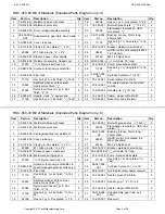
HDC-450-60 Bill of Materials (Exploded Parts Diagram on p. 4) 

HDC-450-72 Bill of Materials (Exploded Parts Diagram on p. 6) 

Item 

Part no. 

Description 

Qty.  Item 

Part no. 

Description 

Qty. 

1 09-514-156  Weldment, base with mast 

17 

16-145-031  Bolt with grease zerk, 

1

/

2

”-13x3

1

/

2

” 2 

2 09-514-144  Weldment, pivot arm 

18 

33008 

Flat washer, low carbon, USS, zinc 
plated, 

3

/

8

” 

3 09-538-005  Carriage/saddle drum weldment 

19 

09-516-004-

A3 

Bushing, bronze, 37mm long, 
20mm shaft 

4 09-024-002  Cover, tube cap 

20 

38623 

HHCS, metric, zinc plated, 8.8 
M8x1.25x60mm 

5 33-112-034  Clevis pin, zinc plated, 

3

/

4

” x 3

3

/

4

” 

21 

40163 

M8-1.25 Nylock nut 

45286 

#11 hitch pin clip, 

1

/

8

” x 2

5

/

8

” 

22 

09-516-079  Bracket, weldment, small door 

7 09-016-087  Bracket, spacer, cradle arm 

23  09-002-004-A 

3

/

16

” coil chain, 33” long 

8 09-516-006  Weldment, swinging door 

24 

01-016-018  Pump, manual, base plate 

9 37030 

1

/

2

”-13 Nylon insert lock nut 

25 

11105 

Hex bolt, gr. A, zinc plated, 

3

/

8

”-

16x1” 

10 99-640-005 

Hydraulic foot pump, autoshifter, 2-
speed (manual hydraulic units only) 

1 26 

99-021-904-

001 

Cylinder, hydraulic, 1

1

/

2

” x 18” 

11 16-132-350  Floor lock 

27 

99-612-001  Nut & bolt combo, caster receiver 

12 11119 

Hex bolt, gr. A, zinc finish, 

3

/

8

”-16 x 

4” 

28 

16-132-021  Caster, swivel, PU-5/2-S 

13 33622 

Split lock washer, carbon steel, 
medium zinc finish, 

3

/

8

” 

2 29 13-025-023 

Handle, 

grip, 

1

1

/

8

” I.D., red 

14 37024 

Nylon insert lock nut, gr. 2, zinc 
finish, 

3

/

8

”-16 

30 

16-132-216  Caster, wheel, GFN-8/2-W 

15 11129 

Hex bolt, gr. A, zinc finish, 

3

/

8

”-16 x 

48” 

2 31 

09-516-004-

001 

Subassembly, gear train, pull 
chain 

16 

36106 

Hex nut, gr. A, zinc plated, 

3

/

8

”-16 2 

32 

15-023-001 

Reservoir 

Содержание HDC-450 Series

Страница 1: ...DC 450 84 Exploded Parts Diagram and Bill of Materials 7 8 HDC 450 96 Exploded Parts Diagram and Bill of Materials 8 9 Hydraulic System Foot Pump Standard Units Operation Purging Air from the Pump Pur...

Страница 2: ...he drum handler The product is labeled with its capacity see Label 287 in Labeling diagram on p 25 Capacity is reduced to 500 pounds whenever a drum is half full or less Inspect the product as directe...

Страница 3: ...1 16 493 16 547 8 453 4 1091 4 60 773 8 800 lb 364 kg 533 lb 243 kg HDC 450 72 91 11 16 41 11 16 49 3 16 54 7 8 45 3 4 109 1 4 72 92 1 2 800 lb 364 kg 535 lb 243 kg HDC 450 84 110 9 16 4511 16 533 16...

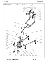
Страница 4: ...Rev 9 25 2017 HDC 450 MANUAL Copyright 2017 Vestil Manufacturing Corp Page 4 of 26 HDC 450 60 Exploded Parts Diagram Bill of Materials on p 5...

Страница 5: ...1 33 16 132 216 Caster wheel GFN 8 2 W 2 17 11129 Hex bolt gr A zinc finish 3 8 16x8 2 34 15 023 001 Reservoir non structural 1 HDC 450 60 Bill of Materials Exploded Parts Diagram on p 4 HDC 450 72 Bi...

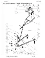
Страница 6: ...Rev 9 25 2017 HDC 450 MANUAL Copyright 2017 Vestil Manufacturing Corp Page 6 of 26 HDC 450 72 Exploded Parts Diagram Bill of Materials on p 5...

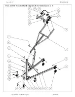
Страница 7: ...Rev 9 25 2017 HDC 450 MANUAL Copyright 2017 Vestil Manufacturing Corp Page 7 of 26 HDC 450 84 Exploded Parts Diagram Bill of Materials on p 8...

Страница 8: ...025 023 Handle grip 11 8 I D red 2 16 09 112 029 Pin clevis 2 32 09 516 004 001 Subassembly gear train pull chain 1 33 15 023 001 Reservoir 1 HDC 450 96 Exploded Parts Diagram Exploded Parts Diagram o...

Страница 9: ...Rev 9 25 2017 HDC 450 MANUAL Copyright 2017 Vestil Manufacturing Corp Page 9 of 26 HDC 450 96 Exploded Parts Diagram Bill of Materials on p 8...

Страница 10: ...s at a controlled rate Do not increase the pressure relief setting more than necessary i e be sure that you do not exceed the pressure rating of the components in the hydraulic system Purging Air from...

Страница 11: ...n the rear and the other is located on the right side of the pump body Including 2 pressure ports and 2 intake return ports allows the circuit configuration to be adapted to varied applications The un...

Страница 12: ...sure compensated 1 0 gal 1 7 99 114 001 Washer beveled spring washer 8 8 99 146 008 Spring relief 1 9 99 653 005 Assembly release valve packing 1 9 1 99 031 022 Accessory hydraulic relief valve pin se...

Страница 13: ...ly OR I can pump the pedal but the arm does not move g Pump is air locked h Debris on seat of inlet check valve i Pressure setting of relief valve needs adjustment j Debris on seat of relief valve g R...

Страница 14: ...her 1 9 15 533 013 Cable battery 23 black 1 10 15 533 014 Cable battery 23 red 1 11 23305 33688 33008 3 8 16 x 1 utility grade bolt 3 8 high collar lock washer 3 8 flat washer 2 2 2 12 99 135 011 4 12...

Страница 15: ...Description Qty 31 568 015 BN70 O ring 1 32 568 011 BN70 O ring 1 33 99 153 058 Valve cartridge normally closed 1 34 99 034 010 Coil with weather tite plug 1 35 99 153 006 Valve pressure relief 1 36 5...

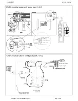
Страница 16: ...Rev 9 25 2017 HDC 450 MANUAL Copyright 2017 Vestil Manufacturing Corp Page 16 of 26 12VDC modular power unit layout part 2 of 2 12VDC modular power unit layout part 1 of 2...

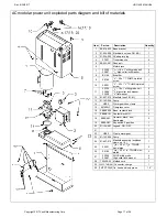
Страница 17: ...688 33008 3 8 16 x 1 utility grade bolt 3 8 high collar lock washer 3 8 flat washer 2 2 2 12 01 627 010 Manifold see FIG 6C 1 13 01 143 906 Pump 1 14 HS52 Worm gear hose clamp 1 15 091802JY Fiberglass...

Страница 18: ...enclosure plate 1 9 C500 3 8 1 2 knockout Romex 2 screw NM clamp connector 4 10 01 127 010 LHL standard manifold 3 boss 1 11 6801 06 06 NOW 3 8 16 x 1 utility grade bolt 2 12 99 153 011 Check valve 1...

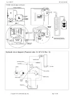
Страница 19: ...Rev 9 25 2017 HDC 450 MANUAL Copyright 2017 Vestil Manufacturing Corp Page 19 of 26 Hydraulic circuit diagram Powered units 01 127 010 Rev C 115VAC modular power unit layout Cylinder...

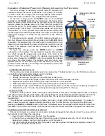
Страница 20: ...might occasionally need to be cleaned see Troubleshooting on p 24 25 Before working on any part of the hydraulic system always lower the carriage 1 Remove the cover from the power unit 2 Identify the...

Страница 21: ...d electrical inlet The inlet projects through the cover housing of the power unit The user must provide a 3 prong charging cord appropriate for line and motor voltages The charger is current limited a...

Страница 22: ...Hinged doors Gear handle Saddle in horizontal position 4 Lift the drum just a few inches above the ground using either the foot pump standard units or modular power unit HDC DC and HDC AC options Ins...

Страница 23: ...nections 4 Frame elements inspect the legs vertical members and braces for cracked welds bends etc 5 Saddle drum retainer and pivot arm visually examine each element for damage Pay particular attentio...

Страница 24: ...verloaded o Inoperative pump k Lower the carriage Remove the lowering solenoid valve and clean Refer to p 20 l Correct as appropriate See also 2 f h m See 1 b n See 2 e o See 2 j 4 Motor labors or is...

Страница 25: ...el that is damaged and or not easily readable Numbers below label images in the diagram correspond to the identification number of each label C Label 287 applied to upright frame member A Label 220 ap...

Страница 26: ...e warranty covers defects in the following original dynamic components motors hydraulic pumps electronic controllers switches and cylinders It also covers defects in original parts that wear under nor...

Отзывы: