Rev. 9/25/2017
HDC-450, MANUAL
Copyright 2017 Vestil Manufacturing Corp. Page 20 of 26
Operation of Modular Power Unit (Raising & Lowering the Pivot Arm):
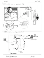
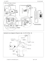
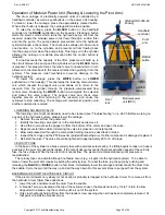
The drum carriage of electrically powered units is controlled by a
handheld controller as well as pushbuttons on the power unit housing.
To raise or lower the carriage, press the appropriately marked button.
When either button is released, the carriage will maintain position.
To raise the carriage, press the
BLACK
button on the handheld
controller (or the
RAISE
pushbutton on the housing). Pressing a button
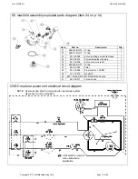
starts the electric motor which turns the hydraulic pump. Oil from the
reservoir (inside the modular power unit) flows through a suction filter
and into the pump. The pump delivers pressurized oil to the hydraulic
cylinder through a check valve. The check valve allows oil to flow only in
one direction, i.e. to the cylinders, and prevents oil from flowing back
into the pump circuit when the pump stops. This traps oil in the cylinder
allowing the carriage to maintain elevation after the control button is
released.
If a load exceeds the capacity of the lifter, pressure will build up in
the circuit between the pump and the cylinders when the
BLACK
button
is pressed. This pressure forces the relief valve to unseat which in turn
allows oil to circulate back to the reservoir rather than pushing it into the
cylinder. This pressure relief mechanism prevents damage to the
hydraulic system.
To lower the carriage, press the
WHITE
button (or
LOWER
pushbutton on the housing). This energizes the lowering solenoid valve
coil, which unseats the poppet valve and allows oil to return to the
reservoir from the cylinder through the pressure-compensated flow
control valve. Releasing the
WHITE
button de-energizes the solenoid
and closes the valve poppet. The poppet valve and check valve
together prevent oil from returning to the reservoir and cause the
cylinders to stop retracting. The carriage will maintain its position until
another command is received.
LOWERING SOLENOID VALVE
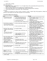
The lowering valve might occasionally need to be cleaned (see “Troubleshooting” on p. 24-25. Before working on
any
part of the hydraulic system, always lower the carriage.
1. Remove the cover from the power unit.
2. Identify the lowering valve (port LL in the manifold) and remove it.
3. Use a thin tool to press the poppet in (from the bottom of the valve) and open the valve.
4. Repeat several times while immersing the valve in kerosene or mineral spirits.
5. Blow compressed air through the valve while holding it open as described in step 3.
6. Inspect the O-rings and the PTFE washer (polytetrafluoroethylene). If either component is damaged, replace it.
7. Reinstall the valve. The valve should be tightened to approximately 20 ft.-Ib. of torque.
VELOCITY FUSE
In the base of the cylinder is a brass velocity fuse with a stainless steel spring. If a fitting begins to leak or a hose is
punctured, the pivot arm descends rapidly. If the rate of descent exceeds the preset activation speed of the velocity
fuse, the fuse closes. While the fuse is shut oil cannot flow. The pivot arm remains stationary until pressure is
reestablished.
The velocity fuse can activate although no failure occurs (e.g. air gets into the hydraulic system). To be able to
raise or lower the pivot arm requires resetting the velocity fuse. To reset the fuse, jog the pump by pushing and
releasing the
BLACK
(or
RAISE
)
button a few times. Immediately lower the carriage and disconnect the drum from
the saddle. Cycle the pivot all the way up and all the way down. Do this several times to purge air from the system.
BLEEDING AIR FROM THE HYDRAULIC CIRCUIT
If the pivot arm lowers very slowly (or not at all), air probably is trapped in the hydraulic circuit. To remove air from
the hydraulic circuit, follow these directions.
1. Lower the arm and disconnect the drum from the saddle.
2. A “bleeder” screw is located at the top of the cylinder. Loosen the bleeder screw by 1/4 to 1/2 turn to allow
trapped air to escape. Jog the motor to push air out of the system.
3. Only clear hydraulic fluid will flow from the bleeder screw opening when air has been completely removed. At
that point, reinstall the bleeder screw.
Handheld
controller
RAISE
button
LOWER
button
Modular power
unit (MPU)
Floor
lock
Pivot
arm
[Model HDC-305-60
shown]

