Subject to modifications.
© Vestamatic GmbH
6/7
G
H O M E · VL-ME-230-45
Art.-Nr.:
1100 001 GB
1518 A08
• Vestamatic GmbH • Dohrweg 27 • D-41066 Mönchengladbach
• www.vestamatic.com
Option: start with lower limit position setting
– Hold down the button
to move the motor in the re-
quested
lower
limit position.
– Press the button
shortly.
– The red LED of button
starts blinking as long as the
limit setting process is in progress.
– The red LED of button
lit solid if the process is finished.
– Hold down the button
till motor stops automatically
due to obstacle detection. Upper physical limit position
is now set.
– The motor needs the following complete movements
(figure 3) to memorize the limit position. (Hold down the
button
or
to move the motor in the requested
direc tion). The motor will give a feedback (short up / down
movement) to confirm that the installation procedure has
ended.
Physical – Virtual
Advice: start with upper limit position setting
– Hold down the button
till motor stops automatically
due to obstacle detection. Upper physical limit position
is now set.
– Hold down the button
to move the motor in the re-
quested
lower
limit position.
– Press the button
shortly.
– The red LED of button
starts blinking as long as the
limit setting process is in progress.
– The red LED of button
lit solid if the process is finished.
– The motor needs the following complete movements
(figure 2) to memorize the limit position. (Hold down the
button
or
to move the motor in the requested
direc tion). The motor will give a feedback (short up / down
movement) to confirm that the installation procedure has
ended.
UP
DOWN
red
Change
turning
direction
green
yellow
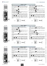
Fig. 2
Fig. 3
Option: start with lower limit position setting
– Hold down the button
till motor stops automatically
due to obstacle detection. Lower physical limit position is
now set.
– Hold down the button
till motor stops auto matically
due to obstacle detection. Upper physical limit position
is now set.
– The motor needs the following complete movements
( figure 7) to memorize the limit posi tion. (Hold down the
button
or
to move the motor in the requested
direc tion). The motor will give a feedback (short up / down
movement) to confirm that the installation procedure has
ended.
Physical – Physical
Advice: start with upper limit position setting
– Hold down the button
till motor stops auto matically
due to obstacle detection. Upper physical limit position
is now set.
– Hold down the button
till motor stops automatically
due to obstacle detection. Lower physical limit position is
now set.
– The motor needs the following complete movements
( figure 6) to memorize the limit posi tion. (Hold down the
button
or
to move the motor in the requested
direc tion). The motor will give a feedback (short up / down
movement) to confirm that the installation procedure has
ended.
UP
DOWN
red
Change
turning
direction
green
yellow
Fig. 6
Fig. 7
Advice: start with upper limit position setting
– Hold down the button
to move the motor in the re-
quested
upper
limit position.
– Press the button
shortly.
– The
green
LED of button
starts blinking as long as
the limit setting process is in progress.
– The
green
LED of button
lit solid if the process is
finished.
– Hold down the button
till motor stops automatically
due to obstacle detection. Lower physical limit position is
now set.
– The motor needs the following complete movements
(figure 4) to memorize the limit position. (Hold down the
button
or
to move the motor in the requested
direc tion). The motor will give a feedback (short up / down
movement) to confirm that the installation procedure has
ended.
Virtual – Physical
Option: start with lower limit position setting
– Hold down the button
till motor stops automatically
due to obstacle detection. Lower physical limit position is
now set.
– Hold down the button
to move the motor in the re-
quested
upper
limit position.
– Press the button
shortly.
– The
green
LED of button
starts blinking as long as
the limit setting process is in progress.
– The
green
LED of button
lit solid if the process is
finished.
– The motor needs the following complete movement
(figure 5) to memorize the limit position. (Hold down the
button
to move the motor in the requested direction).
The motor will give a feedback (short up / down movement)
to confirm that the installation procedure has ended.
UP
DOWN
red
Change
turning
direction
green
yellow
Fig. 5
Fig. 4


