Subject to modifications.
© Vestamatic GmbH
3/7
G
H O M E ∙ VL-ME-230-45
Art.-Nr.:
1100 001 GB
1518 A08
• Vestamatic GmbH • Dohrweg 27 • D-41066 Mönchengladbach
• www.vestamatic.com
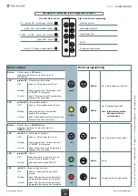
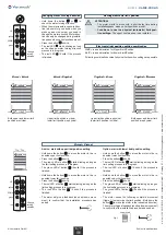
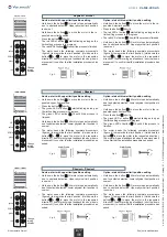
Electronic limit position setting with Installation tool
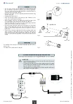
How to connect to an Installation tool (VL-Progset-ME/SMI-230 / Art.-no.: 54185775).
IMPORTANT!
– Switch off the power supply. Connect the wire of the motor to the terminal
clamps of the installation tool.
– It is important that the motor-wire-colors correspond with the installa-
tion-tool-wire-colors, otherwise the motor turning direction could be set
incorrect. Switch on the power supply.
– The installation tool is not suitable for continuous operation and has only
been used for set the limit position.
Ä
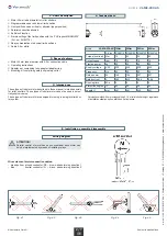
– The connection cable should be installed in an conduit to the junction
box, in compliance with the local building and electrical regulations.
Avoid any contact between moving objects and connection cables by
routing the cables according to figure 1.
– Move the roller shutter or screen completely down before disconnecting
the tube connectors.
– Dissasembly of tubular shaft.
– Place the mounting bracket to the desired position. Assembly of the
motor can be performed on both sides.
– Slide the Adapter ring (A) on the adjustment ring (B). Be aware of the
correct installation of the notch with the Adapter (D), (figure 2).
– Place the tube adapter (E) on to the motor axle (F) and secure it with the
safety clip (G) that comes within the mounting-kit.
– Be careful when sliding the tubular motor completely into the tubular
shaft, until the adapter ring is covered into the tubular shaft, (figure 3).
Under no circumstances external force should be applied to the motor
in any way.
– Place the motor head and tubular shaft into the mounting bracket and
check for proper fit. Secure the square pin of the motor head with the
safety cotter that comes with the mounting-kit. Make sure to install the
motor in a position that the adjustment screws are accessible from the
outside.
Assembly
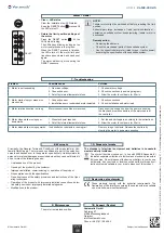
Fig. 1
Fig. 2
Fig. 3
Disassembly
The workflow is the same as in the section “Assembly” (see above) but in
reverse order.
The setup of limit positions can be skipped.


