Subject to modifications.
© Vestamatic GmbH
Ar
t.-Nr
.:
85301221 E1 •
V
estamatic GmbH • Dohrw
eg 27 • D-41066 Mönchengladbach • www
.v
estamatic.com
IF SMI RS-485
5/ 7
G
Status Bit layout
Bit 7 Bit 6 Bit 5 Bit 4 Bit 3 Bit 2 Bit 1 Bit 0
Meaning
X
X
X
X
0
X
X
X
MOTOR ERROR OCCURED
X
X
X
X
1
0
0
0
UP + DOWN + STOP
X
X
X
X
1
0
0
1
DOWN + STOP
X
X
X
X
1
0
1
0
UP + STOP
X
X
X
X
1
0
1
1
ALL STOP
X
X
X
X
1
1
0
0
UP + DOWN
X
X
X
X
1
1
0
1
ALL DOWN
X
X
X
X
1
1
1
0
ALL UP
X
X
X
X
1
1
1
1
NOT VALID
1
1
1
1
X
X
X
X
INVALID SMI RESPONSE
5.4.8 MSG_GET_POS2
This message is used to get (read) the stored intermediate position 2.
Message: [SID] / [LEN] / [CMND] / [SMIID] / [CRC16]
[SMIID]:
SMI address of motor (0..15)
Response: [SID] / [LEN] / [CMND] / [SMIID] / [POS0] / [POS1] / [CRC16]
[SMIID]:
SMI address of motor (0..15). When high-nibble of SMI address
is 0xF0, an error occurred during GET_POS2.
[POS0]:
LSB of 16-bit intermediate position 2.
[POS1]:
MSB of 16-bit intermediate position 2.
The intermediate position value is defined as below:
0x0000 is the top position (0%).
0x8000 is the middle position (50%).
0xFFFF is the bottom position (100%).
5.4.9 MSG_SET_POS2
This message is used to set (write) intermediate position 2.
Message: [SID] / [LEN] / [CMND] / [SMIID] / [POS0] / [POS1] /
[CRC16]
[SMIID]:
SMI address of motor (0..15)
[POS0]:
LSB of 16-bit intermediate position 2.
[POS1]:
MSB of 16-bit intermediate position 2.
Response: [SID] / [LEN] / [CMND] / [SMIID] / [POS0] / [POS1] /
[CRC16]
[SMIID]:
SMI address of motor (0..15). When high-nibble of SMI
address is 0xF0, an error occurred during SET_POS2.
[POS0]:
LSB of 16-bit intermediate position 2.
[POS1]:
MSB of 16-bit intermediate position 2.
5.5 Status commands
#define MSG_GETGENSTAT
0xA0
#define MSG_GETDETSTAT
0xA1
5.5.1 MSG_GETGENSTAT
This message requests the general status of the system.
Message: [SID] / [LEN] / [CMND] / [CRC16]
Response: [SID] / [LEN] / [CMND] / [PRES0] / [PRES1] / [RDY0] / [RDY1] /
[CRC16].
[PRES0]:
The LSB mask of the 8 first motors present on the SMI BUS.
[PRES1]:
The MSB mask of the 8 last motors present on the SMI BUS.
[RDY0]:
The LSB mask of the 8 first motors ready to operate on the SMI BUS.
[RDY1]:
The MSB mask of the 8 first motors ready to operate on the
SMI BUS.
Motor can always accept new commands; RDY0/RDY1 indicates if a motor
is running (flag cleared) or motor is idle (flag set).
5.5.2 MSG_GETDETSTAT
This message is used to obtain the detailed status of a specified sunblind.
Message: [SID] / [LEN] / [CMND] / [SMIID] / [CRC16]
[SMIID]:
SMI address of motor (0..15)
Response: [SID] / [LEN] / [CMND] / [SMIID] / [STATUS] / [POS0] /
[POS1] / [TILT] / [CYCLE0] / .. / [CYCLE3] / [CRC16]
[SMIID]:
SMI address of motor (0..15)
[STATUS]: Status of the motor
[POS0..1]: 16-bits absolute position value
[TILT]:
Orientation of the slats
Remark:
Tilt information uses a manufacturer specific SMI command,
which is currently only supported by Vestamatic SMI motors.
For non Vestamatic SMI-motors, TILT value 0x00 is returned.
[CYCLE0..3]: 32-bits cycle counter of the motor
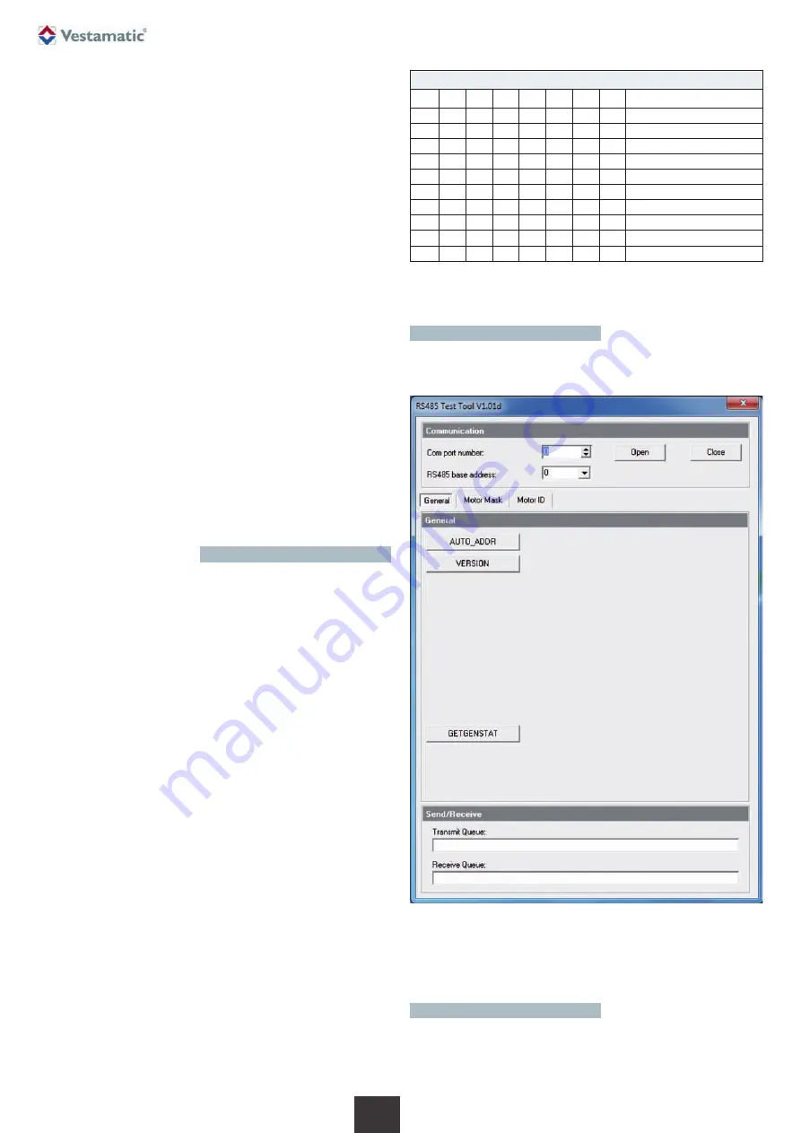
6. PC Test Software
For testing your application, a freeware PC Software (Windows
®
) can be
downloaded from our website
http://www.vestamatic.com.
In the
“Communication”
section, select the RS-485 communication port
of your PC, that is connected to the IF SMI RS-485 module. Also set the
RS-485 base address. This must correspond with the DIP switch settings
on the IF SMI RS-485 module. Press the “Open” button to open the com-
munication channel.
6.1 Communication


