

Vertiv
™
|
Liebert
®
NX
™
225-600kVA Installation Manual | Rev. 8 | 07/2017
35
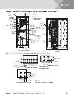
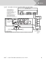
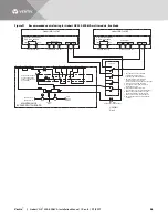
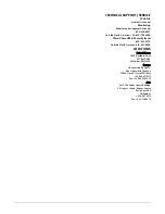
Figure 20
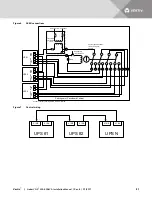
Recommended control wiring for Liebert NX 225-600kVA single module, Eco Mode
NX225-600kVA SMS
Contact closes when
UPS is on bypass
TB4-2
TB4-3
TB1-7
TB3-6
TB3-5
TB1-8
TB3-7
SKRU Status
(To SKRU 842, 840, 841)
(To SKRU 844, 843)
NO
2PDT SW
841
840
842
843
844
821
823
824
820
822
Solenoid Key Release
Unit (Auxiliary switch
shown in position with
key installed)
6
L
X
X
X
Maintenance
Bypass Source
MBB
MIB
Critical
Load
MAINTENANCE
BYPASS SWITCHBOARD
UPS
System
Source
ECO Mode
Enabled (On) Disabled (Off)
1. Key release unit with associated
controls and locking devices
supplied by switchboard provider.
2. Switchboard/gear manufacturer to
provide all wires, pins, sockets,
connectors and proper designation as shown.
3. All wiring to be UL/CSA approved.
4. Wire gauge to be #16 AWG minimum
except where noted.
5. All designated terminal blocks to
be accessible from the front of switchgear.
6. SKRU to be equipped with a two-pole,
double-throw (4P/DT) auxiliary switch.
7. 4PDT switch must be rated at 120VAC.
8. Switch position shown is for Eco-Mode disabled
U3826012
Rev. 0


