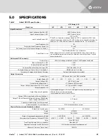
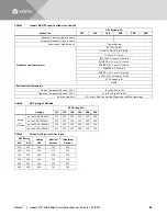
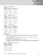


Vertiv
™
|
Liebert
®
NX
™
225-600kVA Installation Manual | Rev. 8 | 07/2017
31
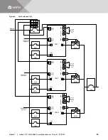
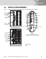
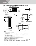
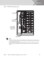
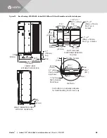
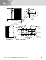
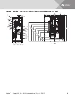
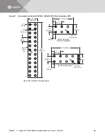
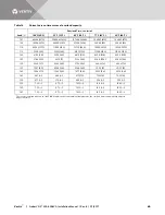
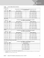
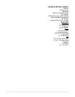
Figure 16
Outline drawing, 400-600kVA Liebert NX, SMS and 1+N multi-module unit with static bypass
1. All dimensions are in inches (mm).
2. 24" (610mm) minimum clearance above
unit required for air exhaust and 36" (914mm)
front access required for service.
3. Keep cabinet within 15 degrees of vertical.
4. Top and bottom cable entry available through removable
access plates. Remove, punch to suit cable entry size
and replace.
5. Unit bottom is structurally adequate for forklift handling.
6. Control wiring and power wiring must be run
in separate cable entry.
7. All wiring is to be in accordance with national
and local electrical codes.
8. Depth dimension includes front door and rear panel.
10. Width dimensions include side panels.
11. See technical data drawing for shipping weights.
11. The height is to the top of the frame; fans rise
1.5" (38.mm) above the frame.
33.7"
(856mm)
33.7"
(856mm)
29.8"
(756mm)
1.5"
(38mm)
2.4"
(62mm)
34.7"
(881mm)
19.3" (489mm)
Center of
Gravity
40.2" (1022mm)
Center of Gravity
Center of Gravity
Typ. for Front
36.8" (935mm)
Power Conduit
Opening without Panel
24.5" x 15.5"
(622mm x 394mm)
Power Conduit
Opening without Panel
24.5" x 15.5"
(622mm x 394mm)
Low Voltage Conduit
Plate to Panel
1.3" (33mm)
33.2"
(844mm)
1.1" (28mm) to Panel
6.5" (165mm)
to Panel
VENT
VENT
Low Voltage
Conduit Plate
2.8" x 11.7"
(71mm x 297mm)
Low Voltage
Conduit Plate
2.9" x 10.9"
(71mm x 276mm)
76.8"
(1950mm)
See Note 12
90.7" (2304mm)
59.1" (1502mm)
31.6"
(802mm)
U38-6C-2001
Rev. 5
RIGHT SIDE VIEW
FRONT VIEW
FRONT
FRONT
BOTTOM VIEW


