Electrical Installation
Vertiv | Liebert CRD10 | User Manual
59
Following is the list of Critical and Secondary fault alarms:
1)
Critical fault alarms: High pressure lock, Low pressure lock, High discharge temperature lock, Low
discharge superheat lock, Low pressure sensor fail lock, Compressor drive fail lock, Fan fail alarm
(Alarm process setting is shut down), Water underfloor alarm (Alarm process setting is shut down),
Power fail alarm (Alarm process setting is shut down).
2)
Secondary fault alarms: High discharge temperature alarm, Air flow temperature sensor failure, Air
flow loss alarm, Discharge temperature sensor failure, Suction temperature sensor failure, Low
pressure sensor failure, EEV drive communication failure, Compressor drive communication failure,
Compressor temperature control sensors failure, Fan temperature control sensors failure, Power fail
alarm (Alarm process setting is fan only), High supply temperature alarm, High return temperature
alarm.
2.
Rotation function
Rotation function is utilized to ensure that all the units have an equal run-time.
3.
Avoid fighting function
Avoid units performing conflicting operations. For example: (a) units are not allowed to heat if other units
are cooling and vice versa, and (b) units are not allowed to humidify if other units are dehumidifying and
vice versa, so the master will calculate the number of cooling run unit and heat run unit, if the cooling run
unit number is bigger than heat run unit, so in the team group, it keep all the cooling unit run, and stop all
the heat unit. It is the same with humidify/dehumidify run unit.
4.
Cascade function
If the run unit
occur “High Temperature alarm”, then auto start a standby uni
t
•
Teamwork connection and setting
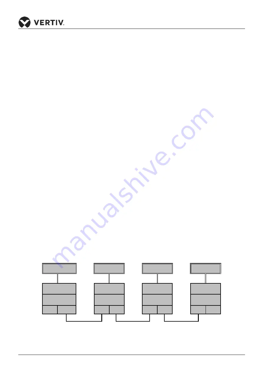
To use the teamwork control function, connect the communication cable to terminals CAN1 & CAN2 port on
the unit. The connection diagram as shown in Figure 4-7:
HMI Touch
HMI Touch
HMI Touch
HMI Touch
Controller
Controller
Controller
Controller
Master 0#
Slave 1#
Slave 2#
……
Slave 15#
CAN1 CAN2
CAN1 CAN2
CAN1 CAN2
CAN1 CAN2
CAN BUS
CAN BUS
CAN BUS
Figure 4-7 The connection diagram of the Teamwork Control


