


10H92873 - rev. 8 - 01/2019 - pag. 11
6.4. APPENDIX B - 80-NET / 70-NET (50-60KVA)
6.4.1. PARAMETERS SETTING
6.4.1.1. ENABLE EXTERNAL SYNCHONISATION CONTROL
Once all the connections are done as per Installation Manual, switch on QS1 on the first UPS and perform the
following steps:
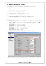
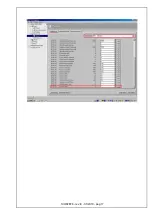
In PPVis -> Parameter Input -> "[10] [CU-Inverter] Inverter Init", set the following parameters:
• PNU 51.0 "Access level CU" set to "Experts - Level 3 (3)";
• PNU 799.0 "SF - Super service" set to "SF 4 (4)";
• PNU 52.0 "Function selection CU" set to "H/W Init - URL (2)";
• PNU 579.0 "Enable External synchronization" set to "Yes (1)";
• PNU 67.1 "VEC_EXT_PHI_OFFSET" set to "0";
• PNU 67.2 "VEC_EXT_SYN_F_LIM" set to "1024";
• PNU 67.3 "VEC_EXT_SYN_PHI_LIM" set to "1024";
• PNU 67.4 "VEC_DELTA_F_GAIN" set to "4096";
Send all the parameters according to the list above (use the send pushbutton);
Once the parameters are at the "Actual Value" return to normal operation as follows:
• PNU 52.0 "Function selection CU" set to "Return (0)";
• PNU 799.0 "SF - Super service" set to "SF 0 (0)";
• PNU 51.0 "Access level CU" set to "Normal Operation - Level (1)";
• Once back in normal operation open QS1 and the electronics will shut down;
Follow these steps for ALL the units connected to ESB.
6.4.2. OFFSET COMPENSATION TUNING
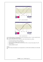
The parameter 67.1 has been designed to compensate the phase error, introduced by the UPS control, between
the frequency reference coming from the ESB and the inverter output signal.
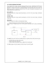
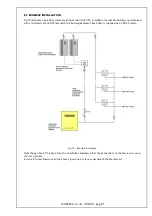
To carry out this procedure an oscilloscope between reserve input and inverter output must be used. The ESB
must be already installed and interconnected to the UPS system. The PNU 579 must be already loaded and
set to 1.
The PNU 67.1 calibration must be done on each UPS composing the system.
Please, perform the following steps:
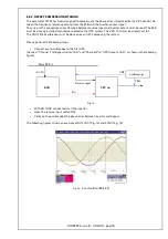
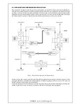
• Connect your oscilloscope to the first UPS;
(Connect "Channel 1" to "Bypass Input L1 & N" and "Channel 2" to "UPS Output L1 & N", as shown in the following
figure)
Fig. 10 -
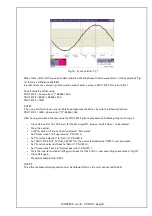
• With NO LOAD connected, start the inverter;
• Open the reserve input switch QS2;
• Verify on the oscilloscope the phase error between inverter and bypass.
ESB
Main BUS A
Reserve input
oscilloscope
UPS An
F
ref
CH1
CH2
(L1-N)
Содержание 10H92873
Страница 2: ...10H92873 rev 8 01 2019 pag 2...
Страница 21: ...10H92873 rev 8 01 2019 pag 17...
Страница 26: ...10H92873 rev 8 01 2019 pag 22...
Страница 43: ...10H92873 rev 8 01 2019 pag 43...
Страница 48: ...10H92873 rev 8 01 2019 pag 48...
Страница 65: ...10H92873 rev 8 01 2019 pag 65...
Страница 70: ...10H92873 rev 8 01 2019 pag 70...
Страница 87: ...10H92873 rev 8 01 2019 pag 87...
Страница 92: ...10H92873 rev 8 01 2019 pag 92...
Страница 109: ...10H92873 rev 8 01 2019 pag 109...
Страница 114: ...10H92873 rev 8 01 2019 pag 114...
Страница 131: ...10H92873 rev 8 01 2019 pag 131...
Страница 136: ...10H92873 rev 8 01 2019 pag 136...
Страница 139: ...10H92873 rev 8 01 2019 pag 139 5 5 1 UPS UPS master UPS slave Puc 3 Puc 3 UPS master 90 NET XT1 100 200 B...
Страница 140: ...10H92873 rev 8 01 2019 pag 140 5 2 Puc 4 90NET B...
Страница 141: ...10H92873 rev 8 01 2019 pag 141 5 3 VERTIV UPS Vertiv Puc 5 Puc 5 Vertiv...
Страница 153: ...10H92873 rev 8 01 2019 pag 153...
Страница 157: ...10H92873 rev 8 01 2019 pag 157 6 7 Puc 19 UPS Vertiv UPS CROSS Puc 19 slave 2 A master...
Страница 158: ...10H92873 rev 8 01 2019 pag 158...
Страница 175: ...10H92873 rev 8 01 2019 pag 175...
Страница 180: ...10H92873 rev 8 01 2019 pag 180...
Страница 197: ...10H92873 rev 8 01 2019 pag 197...
Страница 202: ...10H92873 rev 8 01 2019 pag 202...