


2
—
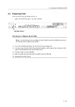
Operating and Maintaining the VX-MD4024
29 / 44
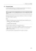
2.3 Controls and LED Indication
The VX-MD4024 has simple controls and indicators on its front panel. The indicators show the
current operating states of various system elements and serve as maintenance aids for local
technicians at each site. The remaining controls on the cards are also provided for local system
testing and maintenance.
In general there are following LED modes:
OFF:
The LED is not powered.
ON:
The LED is powered up constantly.
BLINK:
Alternating between OFF and ON.
Fast-BLINK: Blinking at estimated frequency of 650 ms per on/off cycle
Slow-BLINK: Blinking at estimated frequency of 2700 ms per on/off cycle
SCAN:
The LEDs ON/OFF in sequence.
Table 2-4 VX-MD4024 Controls and LED Indication
VX-MD4024 Front Panel
LED
Color
Indication / Condition
SFP1 - LINK
SFP2 - LINK
Green - On
Valid network connection established
Off
Disconnection
SFP1- ACT
SFP2- ACT
Green - Blink
Transmitting or receiving data
Off
Disconnection
GBE1- Speed
GBE2- Speed
(LED B on RJ-45)
Orange
Off
100 / 1000 Mbps
10 Mbps
GBE1-Link/Act
GBE2-Link/Act
(LED A on RJ-45)
Green - On
Off
Green - Blink
Valid network connection established
Inactive
Transmitting or receiving data
MGMT- Speed
(LED B on RJ-45)
Orange
Off
100 Mbps
10 Mbps
MGMT-Link/Act
(LED A on RJ-45)
Green - On
Off
Green - Blink
Valid Ethernet connection established
Disconnection
Transmitting or receiving data