


32
20304852
ICFDV40 Fireplace Insert
TOUCH SCREEN REMOTE CONTROL OPERATION
thermostat and the regular Thermostat Mode. The icon
“Smart Mode” will appear under the Set Temperature.
The transmitter will automatically adjust the
fl
ame height
according to the difference between the Set temperature
and the Room temperature. There is no manual
fl
ame
height adjustment. The fan speed will also automatically
adjust if turned on.
NOTE:
there will a 10 second delay for the
fl
ame adjust-
ment when the
fi
replace is turned on.
1. When Set Temp. is 3° F or higher than Room Temp.,
fl
ame height will be on High.
2. When Set Temp. is 2° F higher than Room Temp.,
fl
ame height will be on Medium.
3. When Set Temp. is 1° F higher than Room Temp.,
fl
ame height will be on Low.
4. When Set Temp. is equal to Room Temp.,
fl
ame height
does not change (stays on low).
5. When Set Temp. is lower than Room Temp., the
fi
re-
place will be shut off.
6. When Set Temp. is 1° F higher than Room Temp.,
again the
fl
ame height will be on Low.
7. the fan speed follows the
fl
ame height, if the fan is
turned on.
To exit Smart Mode
®
thermostat and shut off the
fi
replace;
a. push and hold the THERMO buttons for 3 seconds,Or
b. press the OFF button, Or
c. slide down on the arrow buttons.
To shut off the Smart Mode
®
thermostat option and return
to regular thermostat mode, press
and hold the THERMO button and
the ON/UP button at the same time
for 3 seconds again.
Blower Speed Control
Figure 46
NOTE:
Blower will only work with
fl
ame on.
The blower speed control function
is used to adjust the speed of the
blower connected to the Signature
Command System. There are four
speed levels, Off, Low, Medium,
High.
1. Press the FAN button to enter the blower speed con-
trol mode. The fan icon will start
fl
ashing.
2. Press the ON/up and OFF/down button to increase/
decrease the blower speed.
3. Press the fan button again to con
fi
rm the speed set-
ting. If the
fi
replace is on, the blower speed will take
effect right away; if the
fi
replace is off, the receiver will
remember this setting and the blower is still off (see
blower On Delay and Off Delay in the next section).
4. After the signal is sent, the ON/up and OFF/down but-
tons become
fl
ame height controller again.
5. When the fan button is
fl
ashing, slide up and down on
the arrow buttons will turn the blower speed to High
or Off directly without pressing the fan button again to
con
fi
rm.
6. If the blower is turned on using the FAN button, the
blower speed will adjust automatically when using
Smart Mode
®
thermostat (See Smart Mode
®
thermo-
stat section).
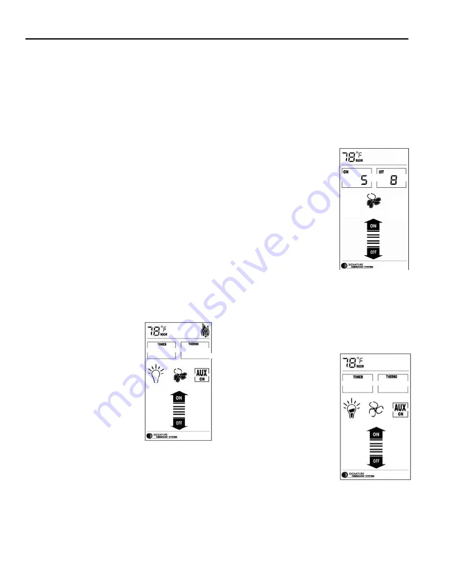
Blower On Delay Time and Off
Delay Time Setup
Figure 47
1. Hold the FAN button for 3 sec-
onds until two numbers appear
on the LCD screen. The left
number is blower On Delay
and the right number is blower
Off Delay Time.
2. When the
fi
rst number is
fl
ash-
ing, use the ON/up button to
set the desired On Delay Time
from 0 to 15 min.
3. Press the OFF/down button to
jump to the Off Delay Time setup.
4. When the second number is
fl
ashing, use the ON/up
button again to set the desired Off Delay Time from 0
to 15 min.
5. Press the OFF/down button again to
fi
nish the setup
and the new settings will be transmitted to the receiver.
6. The default settings are 5 minutes for the On Delay
Time and 8 minutes for the Off Delay Time, as shown.
Light Brightness Control
Figure 48
The light brightness control func-
tion is used to adjust the bright-
ness of the light bulbs connected
to the AC module on the Signature
Command System. There are four
light brightness levels de
fi
ned:
Off, Low, Medium, High
1. Press the LIGHT button to en-
ter the light brightness control
mode. The LIGHT icon will
start
fl
ashing.
2. Press the On/up and OFF/
down buttons to increase/de-
crease the light brightness (Off-Low-Medium-High).
3. Press the light button again to con
fi
rm the setting. The
new setting will be transmitted to the receiver.
Figure 48
Figure 47
Figure 46


