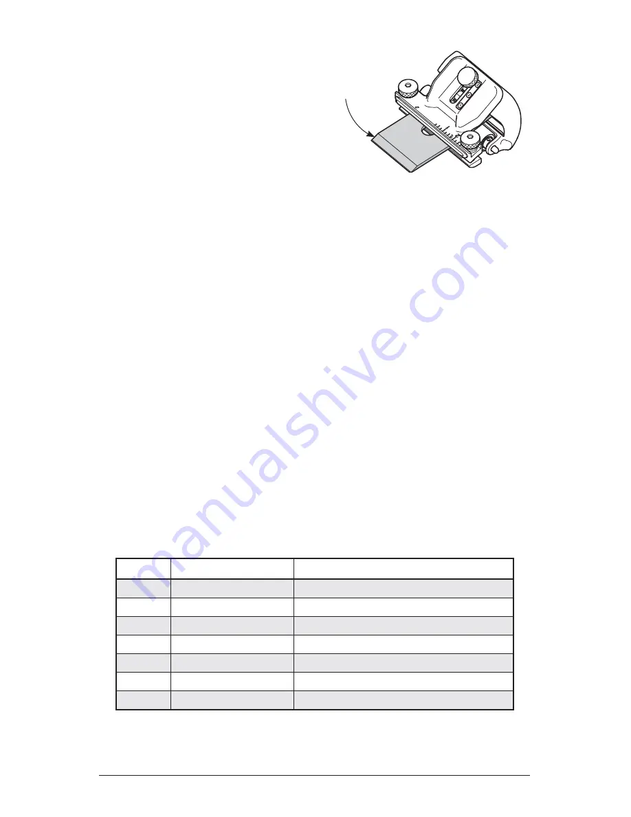
To create back-bevel angles of
10° or higher, simply set the
blade carrier in the
e
(green)
back-bevel confi guration and the
blade registration stop on the
e
(green) scale. Install the blade with
the primary bevel up (as shown in
Figure 11
), and the micro-bevel
knob in the 12 o’clock position.
Back bevels should extend no more
than
1
/
32
"
back from the edge; a few
passes on the abrasive surface should be suffi cient to achieve the desired effect. A
large back bevel will offer no advantages and will require a lot of material removal
from the micro-bevel, should the need arise to remove the back bevel.
Important Note:
In the back-bevel confi guration, the indicated bevel angle
is dependent on blade thickness. The settings on the registration jig have been
calibrated for a
1
/
8
" thick blade. Blade thickness does not have a large effect on
bevel angle, and a blade
3
/
16
" thick will have a bevel angle varying less than 1°
from the registration jig setting.
For a back bevel of 9°, simply remove the registration stop and use the end of the
registration jig as a reference. To remove the stop, fi rst loosen the registration jig clamp
knob, withdraw the registration jig clamp, then slide the stop from the registration jig.
Re-install the registration jig clamp and clamp knob.
To obtain back bevels of less than 9°, you will need to set the micro-bevel knob in
the 6 o’clock position and use a spacer block (see table below for required offset)
underneath the roller. The spacer can simply be a block of hardwood. It is important
that the top surface of the spacer block be parallel with the top of the abrasive surface.
If not parallel, the back bevel will have a skew to it. Once set, mark and save the block
for future use. The spacer will limit the travel of the honing guide, allowing only
short strokes; however, this is not an issue as a back bevel of
1
/
32
"
is suffi cient.
*Note:
The offset is the space you have to create between the spacer and the
abrasive surface. The thickness of the spacer depends on the thickness of your
abrasive material.
Figure 11: Configuration for honing
back bevels.
Offset* Back-Bevel Angle Registration Stop Location
5
/
8
"
8.5°
c
(red) high angle 45°
5
/
8
"
7°
c
(red) high angle 35°
5
/
8
"
6°
c
(red) high angle 30°
5
/
8
"
5°
c
(red) high angle 25°
5
/
8
"
4°
d
(yellow) standard angle 15°
13
/
16
"
3°
c
(red) high angle 30°
13
/
16
"
2°
d
(yellow) standard angle 15°
Blade installed
bevel up.
7
Содержание Mk.II Honing
Страница 1: ...Mk II Honing Guide 05M09 01 U S Pat No 7 553 216 ...
Страница 13: ...05M09 09 Patent Pending Narrow Blade Head ...


