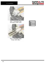
Key
A
Clamp
B
Seal plate
C
'O' Ring seal
D
Seal sleeve
E
Clamp seal
F
End plate
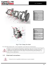
Key
A
Clamp
B
End plate
C
Clamp seal (between Seal
sleeve and Clamp
D
Seal sleeve
E
Seal plate & 'O' Ring seal
(underneath clamp)
F
Tube
Fig 3 'Twin Clamp' End Seal
For assembly details refer to the separate work tube end seal manual.
Under no circumstances should any objects be placed on top of the product.
Always ensure that any vents on the top of the product are clear of any
obstruction. Always ensure all cooling vents and cooling fans (if fitted) are
clear of any obstruction.
2.3
Electrical Connections
Connection by a qualified electrician is recommended.
11
2.0 Installation
Содержание TZF 12/65/550
Страница 7: ...Caution Double Pole Neutral Fusing 7 1 0 Symbols and Warnings ...
Страница 50: ...4 0 2132 Controller 4 7 Navigation Diagram 50 ...
Страница 72: ......
Страница 73: ...Notes Service Record Engineer Name Date Record of Work ...


