11
CONDENSATE DRAINAGE ARRANGEMENT
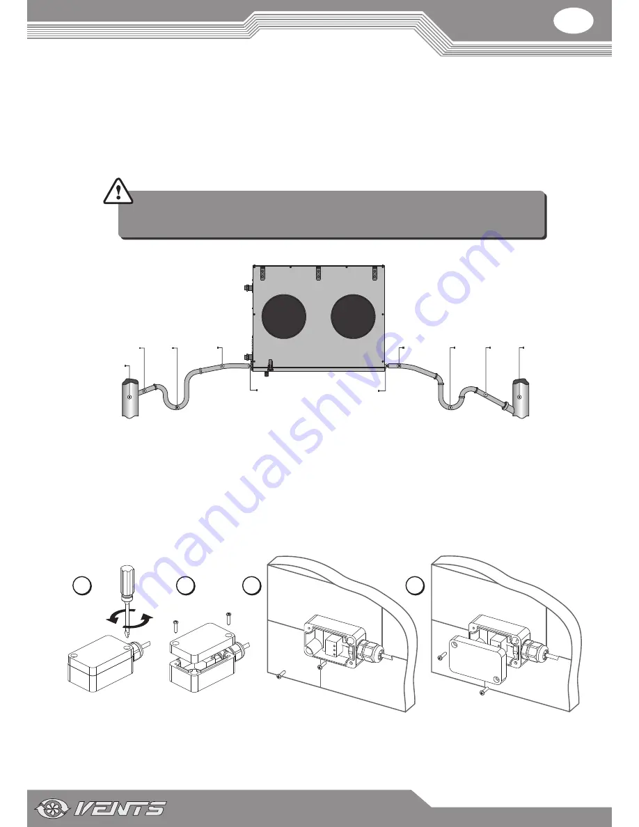
The drain pan is equipped with two drain pipes for condensate removal outside the unit.
Connect the drain pipe, the U-trap (not included in the standard delivery set) and the sewage system with metal, plastic or rubber pipes.
While laying the hoses provide the slope downwards min. 3%. Fill the system with water prior to connecting it to power supply! During
operation the U-trap must always be filled with water. Provide free drainage for the condensed water, otherwise it is accumulated inside the
unit that may cause the equipment damage and condensate outflow to the room.
The condensate drainage system is designed for normal operation in premises with air temperatures above 0 °C! If the expected
ambient air temperatures are below 0 °C the condensate drainage system must be equipped with heat insulation and pre-heating
facilities.
Condensate drain pipe
Pipe
Pipe
Sewage system
U-trap
Pipe
Pipe
Sewage system
U-trap
DO NOT CONNECT SEVERAL DRAIN PIPES FROM SEVERAL AIR HANDLING UNITS TO ONE U-TRAP!
DIRECT CONDENSATE DRAINAGE OUTSIDE WITHOUT CONNECTION TO SEWAGE SYSTEM IS NOT
ALLOWED.
OUTDOOR TEMPERATURE SENSOR MOUNTING AND CONNECTION
The unit is supplied with the TE1 outdoor temperature sensor.
The outdoor temperature sensor mounting is as follows:
1. Remove two screws that retain the sensor cover.
2. Take off the sensor cover.
3. Install the sensor on the outer wall. The installation place must not be subjected to direct solar light.
4. Install the sensor cover back.
5. Connect the sensor to the X1 terminal block in compliance with the electric wiring diagram.
1
3
2
4
Содержание VUT 2000 PW EC
Страница 1: ...VUT 2000 PW EC VUT 3000 PW EC USER S MANUAL Heat recovery air handling unit...
Страница 21: ...V49 1EN 06...


