background image

9

MOUNTING AND SET-UP

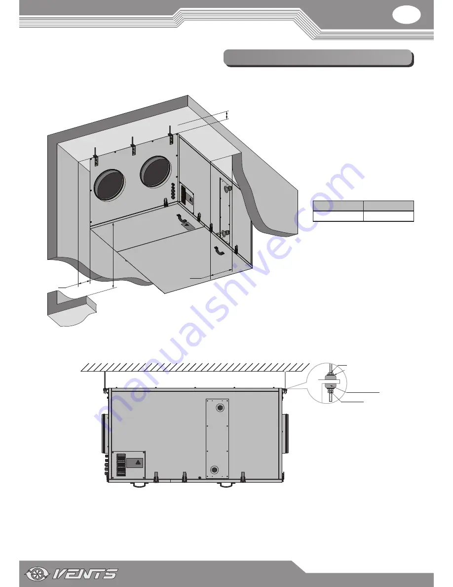
MINIMUM DISTANCE FOR ACCESSING THE UNIT

While mounting the unit provide enough space for its maintenance or repair work.

А

 — minimum distance for 

condensate disposal arrangement. The 

distance is selected depending on the 

installation conditions at the discretion 

of the installer.

b

 — minimum distance for water 

heater connection and condensate 

disposal arrangement. The distance is 

selected depending on the installation 

conditions at the discretion of the 

installer.

С

 — minimum distance from the 

service panel to the floor.

VUT 2000 PW EC VUT 3000 PW EC

1000 mm

1300 mm

min 20 mm

B

A

min C

UNIT MOUNTING

The unit must be suspended to the ceiling on the threaded rod that is fixed inside a dowel.

Washer

Nut

Vibration damping 

rubber

Nut and 

lock-nut

Example 

To attain the best performance of the unit and to minimise turbulence-induced air pressure losses connect a straight air duct section on 

both sides of the unit while mounting. 

Minimum straight air duct length: 

• 

equal to 1 air duct diameter on intake side.

• 

equal to 3 air duct diameters on outlet side.

If the air ducts are too short or not connected, protect the unit parts from ingress of foreign objects, e.g. by covering the spigots with a 

protecting grille or other protecting device with mesh width not more than 12.5 mm to prevent uncontrollable access to the fans.

Содержание VUT 2000 PW EC

Страница 1: ...VUT 2000 PW EC VUT 3000 PW EC USER S MANUAL Heat recovery air handling unit...

Страница 2: ...data 6 Unit design and operating logic 8 Mounting and set up 9 Connection to power mains 13 Functional diagram 14 Technical maintenance 15 Fault handling 17 Storage and transportation rules 17 Manufa...

Страница 3: ...e unit While transferring the unit control the User s manual must be turned over to the receiving operator Symbol legend UNIT MOUNTING SAFETY PRECAUTIONS WARNING DO NOT Disconnect the unit from power...

Страница 4: ...s on it OFF ON Disconnect the unit from power mains prior to maintenance Do not let children operate the unit Do not damage the power cable while operating the unit Do not put foreign objects on the p...

Страница 5: ...tion with heat recovery Mounting method P suspended mounting Air capacity m3 h Control panel __ PU SENS 01 with a sensor display 7 PU JK 01 with an LCD display VUT PB X DESIGNATION KEY The unit with a...

Страница 6: ...B4 500 570 H 761 881 H1 367 427 H2 501 300 L 1400 1835 L1 1453 1888 Unit technical data Model VUT 2000 PW EC VUT 3000 PW EC Unit voltage V 50 60 Hz 1 230 3 400 Max fan power W 2 items 420 2 items 990...

Страница 7: ...he black curve to the pressure drop axis 9 8 kPa How to use water heater diagrams System Parameters Air flow 3500 m3 h Outside air temperature 10 C Water temperature in out 90 70 C Air Speed Starting...

Страница 8: ...e Condensate drain pipe Drain pan Extract filter Control unit Bypass Heat exchanger Bypass damper electric actuator SUPPLY AIR Unit operating logic top view based on VUT 2000 PW EC unit example The ba...

Страница 9: ...000 mm 1300 mm min 20 mm B A min C Unit mounting The unit must be suspended to the ceiling on the threaded rod that is fixed inside a dowel Washer Nut Vibration damping rubber Nut and lock nut Example...

Страница 10: ...ter mode the unit has following temperature limits The unit may not be started when the return heat medium temperature is below 40 C If the return heat medium temperature is 40 C and higher the unit w...

Страница 11: ...s above 0 C If the expected ambient air temperatures are below 0 C the condensate drainage system must be equipped with heat insulation and pre heating facilities Condensate drain pipe Pipe Pipe Sewag...

Страница 12: ...sory and is purchased separately Connect the contact socket of the humidity sensor to the contact socket located inside of the heat recovery unit After that fix the sensor using the clamp and the hold...

Страница 13: ...mper actuator LF230 2 0 75 mm2 SM4 3 way valve actuator LR24 SR 3 0 75 mm2 PK1 Contact from fire alarm panel NO 2 0 75 mm2 P1 Control panel 4 0 75 mm2 TE1 Outdoor air temperature sensor 3 0 75 mm2 1 T...

Страница 14: ...panel Q1 Water heater HV1 Duct humidity sensor HV2 Indoor humidity sensor RK1 Plate heat exchanger SM1 Supply air damper actuator SM2 Extract air damper actuator SM3 Bypass damper electric actuator SM...

Страница 15: ...ntil they slide off the guides Install the filters in the reverse order 2 Heat exchanger cleaning once per year Some dust may accumulate on the heat exchanger block even in case of regular maintenance...

Страница 16: ...Check the drain line operation by filling the drain pan under the unit with water clean the U trap and the drain line if necessary 5 Exhaust louvre shutters and intake diffusers cleaning as required W...

Страница 17: ...r is soiled Clean or replace the extract filter The heat exchanger is frozen Check the heat exchanger for freezing Turn the unit off if required and restart it after the freezing danger is no longer i...

Страница 18: ...ted on the unit packing and in the user s manual user s failure to ensure timely technical maintenance of the unit external damage to the casing excluding external modifications of the unit as require...

Страница 19: ...ate is issued following test carried out on samples of the product referred to above Quality inspector s stamp This is to certify delivery of the complete unit with the user s manual Customer s signat...

Страница 20: ...__________________________________________________________________________________ ___________________________________________________________________________________________________________ _________...

Страница 21: ...V49 1EN 06...

Отзывы: