13
CONNECTION TO POWER MAINS
DISCONNECT THE UNIT FROM POWER MAINS PRIOR TO ANY ELECTRIC INSTALLATION
OPERATIONS. CONNECTION OF THE UNIT TO POWER MAINS IS ALLOWED bY A QUALIFIED
ELECTRICIAN WITH A WORk PERMIT FOR THE ELECTRIC UNITS UP TO 1000 V AFTER CAREFUL
READING OF THE PRESENT USER’S MANUAL. THE RATED ELECTRICAL PARAMETERS OF THE UNIT
ARE SHOWN ON THE RATING PLATE. ANY INTERNAL CONNECTION MODIFICATIONS ARE NOT
ALLOWED AND RESULT IN WARRANTY LOSS.
L N PE 1
L
2
N
3
PE
4
1
5
2
6
3
7
c
8
nc
9
N
10
L
11
N
12
L
13
c
14
nc c
15
no
16
+12V
17
Gnd
Gnd Out
18
B
19
A
20
E+
21 22 23
L
M4
N PE
E+
TE1
+12V Gnd
Gnd Out
P1
B A
1
SM4
2 3
+
Y
1
DD1
2
1
PK1
2
1
SM1
2
1
SM2
Cooler
(no
-c
on
tac
t)
Po
w
er input
230 V
AC
2
N
L
N
L
t°
— ELECTRIC SHOCK HAZARD!
X1
L3
L2
L1
N PE 1
L
2
N
3
PE
4
1
5
2
6
3
7
c
8
nc
9
N
10
L
11
N
12
L
13
c
14
nc c
15
no
16
+12V
17
Gnd
Gnd Out
18
B
19
A
20
E+
21 22 23
L
M4
N PE
E+
TE1
+12V Gnd
Gnd Out
P1
B A
1
SM4
2 3
+
Y
1
DD1
2
1
PK1
2
1
SM1
2
1
SM2
Cooler
(no
-c
on
tac
t)
Po
w
er input
400 V
AC
2
N
L
N
L
t°
— ELECTRIC SHOCK HAZARD!
X1
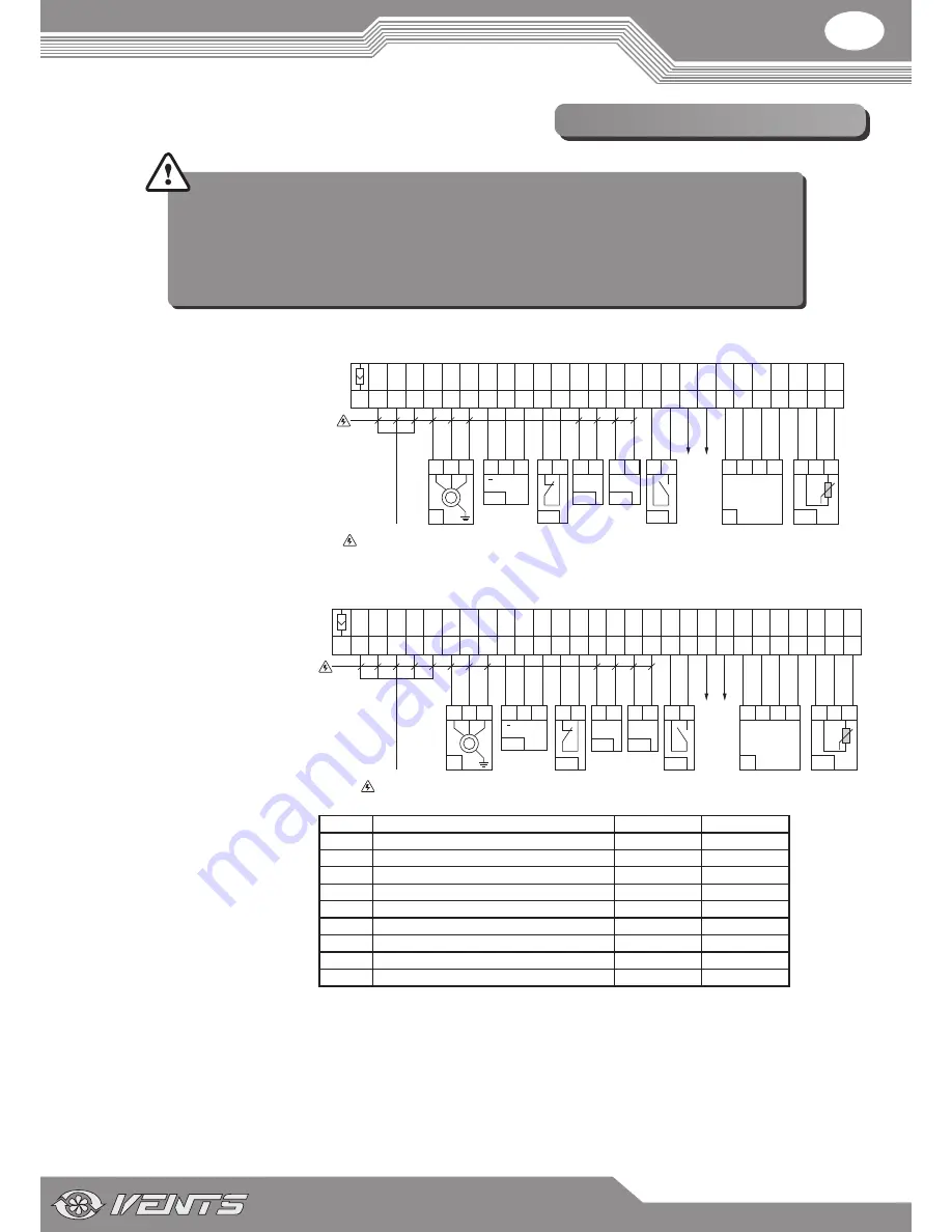
ExTERNAL WIRING DIAGRAM FOR THE UNIT VUT 2000 PW EC
ExTERNAL WIRING DIAGRAM FOR THE UNIT VUT 3000 PW EC
Design.
Name
Model
Wire
Cooler
DX cooler
NO
2 х 0,75 mm
2
DD1
Pump dry run protection relay
NC
2 х 0,75 mm
2
M4
Circulation pump of the heater
max. 0,3 kW
3 х 0,75 mm
2
SM1
Supply air damper actuator
LF230
2 х 0,75 mm
2
SM2
Extract air damper actuator
LF230
2 х 0,75 mm
2
SM4
3-way valve actuator
LR24 SR
3 х 0,75 mm
2
PK1
Contact from fire alarm panel
NO
2 х 0,75 mm
2
P1**
Control panel
4 х 0,75 mm
2
TE1
Outdoor air temperature sensor
3 х 0,75 mm
2
1. The unit delivery set includes P1 and TE1 only.
2. ** - Max. connecting cable length is 20 m.
The VUT 2000-3000 PW EC air-
handling unit is rated for connection
to single-phase AC 230 V / 50 Hz power
mains. The unit must be connected to
power mains using durable, insulated
and heat-resistant conductors (cables
and wires) with minimum cross section
not less than 2.5 mm
2
.
The VUT 2000-3000 PW EC air-
handling unit is rated for connection
to three-phase AC 400 V / 50 Hz power
mains. The unit must be connected to
power mains using durable, insulated
and heat-resistant conductors (cables
and wires) with minimum cross
section not less than 2.5 mm
2
.
The above cross section is for reference only. The applicable cable cross section must be selected depending on the wire type, its maximum
temperature and insulation, the maximum current, the wire length and its installation method.
Use copper wires only.
Connect the unit to power mains through the terminal block located in the terminal box on the side panel of the unit in compliance with the
wiring diagram and terminal marking. Connect all the control and supply cables in compliance with the terminal marking and polarity!
Connect the unit to power mains through the external automatic circuit breaker with a magnetic trip integrated into the fixed wiring system.
The trip current must be in compliance with current consumption.
Содержание VUT 2000 PW EC
Страница 1: ...VUT 2000 PW EC VUT 3000 PW EC USER S MANUAL Heat recovery air handling unit...
Страница 21: ...V49 1EN 06...


