WEATHER CAB SETUP INSTRUCTIONS
Setup - 18
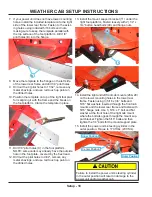
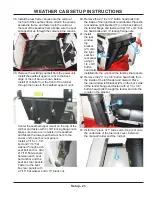
7. If your power unit does not have lower mounting
holes, install the included template onto the right
side of the lower rear frame. Fasten to the exist-
ing holes using included 5/16 bolts and nuts,
making sure to keep the template parallel with
the top surface of the foot platform. Drill 1/8”
pilot holes (B) into the flange.
8.
B
Move the template to the flange on the left side
of the lower rear frame and drill 1/8” pilot holes.
9. Drill out the 4) pilot holes to 11/32”, remove any
metal shavings, and use red touch up paint on
the drilled holes.
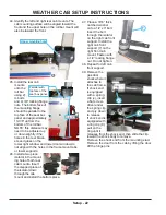
10. Position the template on top of the right foot plat-
form aligning it with the frame and the break on
the foot platform. Clamp the template in place.
11.
C
Drill 1/8” pilot holes (C) in the foot platform.
NOTE: some units may already have the outside
hole in the foot plate, covered by the flex tread.
12. Drill out the pilot holes to 9/32”, remove any
metal shavings, and use red touch up paint on
the drilled holes.
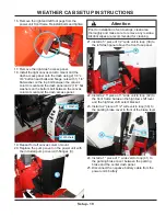
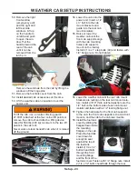
13. Install the mount support bracket (11) under the
right foot platform. Fasten loosely with 2) 1/4” x
3/4” button head bolts (48) and flange nuts.
14.
11
48
26
28
Install the right and left front cab mounts (26 & 28)
on the lower mounting holes in the lower rear
frame. Fasten using 3) 5/16 x 3/4” bolts and
5/16” flat washers inserted through the front cab
mounts and the lower rear frame and fasten with
5/16” flange nuts. Use 1) 5/16 x 1” bolt and flat
washer at the front hole of the right cab mount
where the bolt also goes through the mount sup-
port bracket. Tighten the 5/16” bolts and then
tighten the 1/4” bolts for the mount support plate.
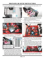
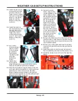
15. Install the power unit’s steering cylinder in the
outer position.
Failure to install the power unit’s steering cylinder
in the outer position will result in damage to the
power unit and/or weather cab.
Inner Position
Center Position
Outer Position
Torque to 170 ft lbs (230 Nm).


