Vent-Axia SOLO Plus Скачать руководство пользователя страница 3

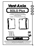
Installation and Wiring Instructions for the SOLO Plus Bathroom Extract Fan. 


  IMPORTANT: 
  READ THESE INSTRUCTIONS 
  BEFORE COMMENCING THE  
  INSTALLATION 

 
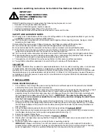
DO NOT install this product in areas where the following may be present or occur: 

  Excessive oil or a grease laden atmosphere. 

  Corrosive or flammable gases, liquids or vapours. 

• 

Ambient temperatures higher than 40°C or less than –5°C. 

• 

Possible obstructions which would hinder the access or removal of the Fan. 


SAFETY AND GUIDANCE NOTES 

A. 

All wiring to be in accordance with the current I.E.E. Regulations, or the appropriate standards of your country 
and 

MUST 

be installed by a suitably qualified person. 

B. 

The Fan should be provided with a local isolator switch capable of disconnecting all poles, having a contact 

separation of at least 3mm. 

C. 

Ensure that the mains supply (Voltage, Frequency, and Phase) complies with the rating label. 

D. 

The Fan should only be used in conjunction with the appropriate Vent-Axia products. 

E. 

It is recommended that the connection to the fan connector terminals is made with flexible cable. 

F. 

When the Fan is used to remove air from a room containing a fuel-burning appliance, ensure that the air 

replacement is adequate for both the fan and the fuel-burning appliance. 

G. 

The Fan should not be used where it is liable to be subject to direct water spray for prolonged periods of time. 

H. 

Where ducted Fans are used to handle moisture-laden air, a condensation trap should be fitted. Horizontal 

ducts should be arranged to slope slightly downwards away from the Fan. 

I. 

This appliance is not intended for use by young children or infirm persons without supervision. 

J. 

Young children should be supervised to ensure that they do not play with the appliance. 


DESCRIPTION 

As standard, the SOLO Plus is suitable for panel/wall installations, flush or surface mounting, either in a horizontal 
or vertical plane. 100mm ducting (flexible or straight) can be attached using the supplied adjustable spigot, 
providing rear or side exit options. Adaptors for System 25 and System 50 ducting can be used in conjunction with 
the adjustable spigot. For wall installations a Wall Kit (25 41 02 White / 25 41 00 Brown) can be used. Please see 
our catalogue or web site (www.vent-axia.com) for more information on System 25/50 and for alternative ducting 
and termination options. 
 

A. INSTALLATION 


PANEL MOUNTING (Surface)


1.  Cut a 105mm

 hole through the panel, ensuring that there is sufficient space for the product to be installed 

and that the filter can be removed for maintenance. 

2.  Removing the Front Assembly [A]. Firstly remove the


Filter [B] (

fig. 2.) 

by squeezing the clips and pulling

Insert 

a small bladed screwdriver into the slots as shown in figure 3 and push gently to release. Lift the front 
assembly slowly from the bottom edge ensuring not to damage the sensor cable (TM model only) attached to 
the front assembly and Base Housing [C] 

(fig. 3/4/11.).


IMPORTANT: The cable for the PIR sensor (TM 

model only) is not connected as supplied but can be removed by carefully unclipping the cable header 
from the Front Assembly [A]

3.  Remove the Spigot Ring [G] from the inside of the Impeller [D] 

(fig. 5.)

 and clip over the Spigot Adaptor [E] 

making sure the lip on the Spigot Ring locates firmly inside the groove on the Spigot Adaptor 

(fig. 6.).

 Ensure 

that the Spigot Adaptor is firmly located onto the Base Housing and the shutter is still securely fastened and 
fully functional. 

4.  Set-up the appropriate speed selection and other features as outlined in 

Section B SETUP. 


5.  Attach the ducting to the Spigot and locate into the hole in the panel ensuring the Skirt [H] is located correctly 

into the Base Housing. Secure into position using appropriate fixtures 

(fig. 7.).


6.  Ensure the Impeller rotates freely. 
7.  Select and follow the appropriate wiring diagram in 

Section C WIRING.


8.  Replace the Front Assembly ensuring that the PIR sensor cable (TM model only) is reconnected to the PIR 

sensor PCB 

(fig. 11.).


9.  Switch the mains power supply on and check the fan is operating correctly. 

IMPORTANT: 

Please note that the T and HT incorporate a switch on delay, which will start the fan after 2 

minutes for the set timeout period. The delay is only activated via the LS and not via the pull-cord or humidity 
sensor (if applicable). If the LS is switched off during the 2 minute period, the fan will remain off.   


3

Содержание SOLO Plus

Страница 1: ...NCTION WITH ILLUSTRATIONS PLEASE SAVE THESE INSTRUCTIONS LISEZ CETTE NOTICE EN CONJONCTION AVEC LES ILLUSTRATIONS RANGEZ LA DOCUMENTATION DANS UN ENDROIT OU VOUS POURREZ LA RETROUVER DIE VORLIEGENDE A...

Страница 2: ...2...

Страница 3: ...n conjunction with the adjustable spigot For wall installations a Wall Kit 25 41 02 White 25 41 00 Brown can be used Please see our catalogue or web site www vent axia com for more information on Syst...

Страница 4: ...to the PIR sensor PCB fig 11 11 Switch the mains power supply on and check the fan is operating correctly IMPORTANT Please note that the T and HT incorporate a switch on delay which will start the fa...

Страница 5: ...5 30 minutes by altering the adjuster on the control PCB T fig 13 i To REDUCE the operating time turn the adjuster T ANTI CLOCKWISE ii To INCREASE the operating time turn the adjuster T CLOCKWISE IMP...

Страница 6: ...ia Guarantee Applicable only to products installed and used in the United Kingdom For details of the Guarantee outside of the United Kingdom contact your local supplier Vent Axia guarantees this produ...

Страница 7: ...standard le SOLO Plus convient aux installations sur panneaux et sur murs aux montages affleurant ou en surface et en position horizontale ou verticale L adaptateur d assise ajustable fourni permet de...

Страница 8: ...i e et les autres fonctions en suivant les instructions de la section B REGLAGE 6 Raccorder la conduite l assise et pousser dans l orifice du panneau en v rifiant que le c ble entre dans la base du bo...

Страница 9: ...PENDANT L INSTALLATION ET L ENTRETIEN 1 OPTION LENTE CONSTANTE Poser le cavalier de vitesse lente constante TR Fig 12 avec la t te de cavalier fournie pour s lectionner la vitesse lente constante L op...

Страница 10: ...ropri Fig 14 15 1 S lectionner et suivre le sch ma de c blage appropri Fig 14 15 2 Il peut tre n cessaire de faire passer le c ble de secteur autour entre l ext rieur de la base du bo tier C et l emba...

Страница 11: ...e mati re ou de fa on Si une pi ce se r v lait d fectueuse ce produit sera r par ou la discr tion de la compagnie sera remplac gratuitement condition 5 qu il ait t install et utilis conform ment aux i...

Страница 12: ...inen r ckseitigen oder seitlichen Ausgang erm glicht Der Adapter f r die Abluftleitung System 25 und System 50 kann in Verbindung mit dem verstellbaren Stutzenteil verwendet werden F r die Wandmontage...

Страница 13: ...nsch der Dicke der Platte entsprechend genug Platz sodass die Klammern hinter der Platten auffedern k nnen 5 Stellen Sie die entsprechende Geschwindigkeitseinstellung und andere Merkmale gem Teil B EI...

Страница 14: ...r LS aktiviert und nicht ber Zugschalter oder Feuchtigkeitssensor falls zutreffend Wenn der LS w hrend der zweimin tigen Verz gerung ausgeschaltet wird bleibt der L fter abgestellt B EINSTELLUNG ACHTU...

Страница 15: ...n aus Abb 14 15 2 Es kann sein dass das Netzkabel zwischen der Au enseite des Hauptgeh uses C und der Einfassung H herumgelegt werden muss damit das Kabel nicht eingeklemmt wird 2 Es kann sein dass da...

Страница 16: ...ass ein Teil des Produkts defekt ist wird das Produkt repariert oder nach Ermessen von Vent Axia kostenlos ersetzt sofern folgende Bedingungen erf llt sind 1 Das Produkt wurde gem der mit jeder Einhei...

Страница 17: ...us geschikt voor paneel muurinstallaties verzonken of oppervlaktemontage ofwel in horizontale of verticale positie Er kan 100 mm kanaal buigbaar of recht worden aangehecht onder gebruikmaking van een...

Страница 18: ...l zodat de clips kunnen openspringen achter het paneel 5 Stel de geschikte snelheidskeuze in en andere eigenschappen zoals aangegeven in Deel B INSTELLING 6 Bevestig de kanalisering aan de spon en pla...

Страница 19: ...rdt uitgeschakeld gedurende 2 minuten zal de ventilator uit blijven B INSTELLING WAARSCHUWING DE VENTILATOR EN DE HULPCONTROLE UITRUSTING MOETEN WORDEN GE SOLEERD VAN DE STROOMTOEVOER TIJDENS DE INSTA...

Страница 20: ...ngsschema fig 14 15 2 Het kan nodig zijn de stroomkabel rond te leiden tussen de buitenkant van de onderste behuizing C en de ommanteling H om te vermijden dat de kabel vast raakt 3 Controleer of alle...

Страница 21: ...een onderdeel defect is wordt het product hersteld of wordt het wanneer de Onderneming dit beslist vervangen op haar eigen kosten op voorwaarde dat het product 1 Werd ge nstalleerd en gebruikt overeen...

Страница 22: ...Fig 2 Abb 2 Fig 4 Abb 4 Fig 3 Abb 3 Fig 5 Abb 5 G F E C A Fig 1 Abb 1 H D B 22...

Страница 23: ...Fig 6 Abb 6 Fig 7 Abb 7 Fig 8 Abb 8 Fig 9 Abb 9 23 Fig 10 Abb 10 Fig 11 TM only TM uniquement nur TM Enkel TM Abb 11 O P...

Страница 24: ...anding met zekering 3A Fig 14 Abb 14 Solo Plus LoWatt P TM Fuse Fusible Sicherung Zekering 1 Phase Supply Alimentation monophas e Einphasen Stromversorgung 1 fasige stroomtoevoer 220 240 V 50Hz Fan Ve...

Страница 25: ...m 105mm WALL MOUNTING Surface MONTAGE MURAL surface WANDEINBAU Aufputzmontage MUURMONTAGE Oppervlakte PANEL MOUNTING Surface MONTAGE SUR PANNEAU surface PLATTENEINBAU Aufputzmontage PANEELMONTAGE Oppe...

Страница 26: ...26...

Страница 27: ...27 190mm 240mm PANEL MOUNTING Flush MONTAGE SUR PANNEAU affleurant PLATTENEINBAU Unterputzmontage PANEELMONTAGE Verzonken...

Страница 28: ...28 Head Office Fleming Way Crawley West Sussex RH10 9YX Tel 01293 526062 Fax 01293 551188 Internet site at www vent axia com 427957 D 08 04...

Отзывы: