4
ENGLISH
In case of overload the vibrator enter into protection mode and to restart it is necessary to remove the supply
voltage, wait about 5 seconds and restart.
Check that the current draw does not exceed the nameplate value. If this is not the case:
-
Check that the flexible system and structural elements comply with the current use requirements.
-
Reduce the vibration force by adjusting the weights until the absorbed current value returns within nameplate
values.
Remember to operate the electric rotary vibrator for short periods during set- up in order to prevent damage to
both the vibrator itself and to the structure in the event of faults.
The vibrator must always be started/stopped by setting the power switch to the ON/OFF position respectively.
3.1
REGULATING THE VIBRATION INTENSITY
ATTENTION: This operation must only be carried out by specialized personnel after the electrical power supply
has been disconnected.
-
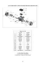
Remove the weight covers (n° 3, page 16).
-
Unscrew the nuts at the shaft ends (n°4, page 16).
-
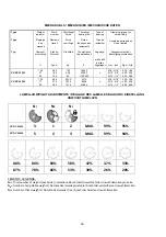
Turn the adjustable weights (n° 7, page 16) on both sides until they have been regulated in the required way, as
shown by the graduated disc (N° 9, page 16) as percentage of the maximum centrifugal force.
If
lamellar
weights
are
installed,
see
page
18.
-
Tighten the nuts and reassemble the weights covers, checking that the seals (n° 6, page 16) are on good conditions
and have correctly fitted into their housings.
3.2 MAINTENANCE
The vibrators need no particular maintenance.
Before servicing a vibrator, wait until the temperature of its casing is not more than 40°C and check that it has
been disconnected from the electricity supply.
Only use genuine VENANZETTI spare parts.
3.2.1 VV-DC 3/100-S08 MF and VV-DC 3/200-S08 MF (page 42-43)
To replace internal parts the vibrator must be disassembled according with the following indications:
-
Disconnect the electricity supply and remove the vibrator from the vibrating machine.
-
Remove the weight covers (n°3).
-
Unscrew the nuts in the shaft ends and remove the weights (n°4-7-9).
-
Remove the two seeger rings mounted on the flanges near to the bearings (n°40).
-
Press the shaft from one side. The shaft will drag at one bearing while one remains in its flange.
-
Remove the bearing from the shaft and remove the other bearing from the flange.
-
Check the bearing seats in the flange and in the shaft. If they are worn the motor group or the shaft must be
replaced.
-
Take new original ball bearings.
-
Press the first new bearing in a flange paying attention that it remains just beyond the seat of the seeger ring, then
mount the seeger ring.
ATTENTION: the shaft is not symmetrical: in one side the bearing seat diameter is bigger than the other side. In the
bigger seat the bearing has to be pressed into it, in the other seat the bearing enter free.
-
Press mount the second new bearing in the bigger seat (n°28)


