background image

124

106309-03 - 4/19

XIII.  Service Parts 

(continued)

Содержание Phantom-X Series

Страница 1: ...ry or loss of life For assistance or additional information consult a qualified installer service agency or the gas supplier This boiler requires a special venting system Read these instructions caref...

Страница 2: ...rds FOLLOW ALL INSTRUCTIONS and warnings printed in this manual the owner s manual and posted on the boiler MAINTAIN THE BOILER To keep your boiler safe and efficient have a service technician maintai...

Страница 3: ...nce or the supply piping See the Water Piping and Trim Section of this manual for details This boiler is supplied with safety devices which may cause the boiler to shut down and not re start without s...

Страница 4: ...ate shall be permanently mounted to the exterior of the building at a minimum height of eight 8 feet above grade directly in line with the exhaust vent terminal for the horizontally vented gas fueled...

Страница 5: ...and Trim 43 VII Gas Piping 55 VIII Electrical 60 IX System Start Up 71 X Operation 80 A Overview 80 B Supply Water Temperature Regulation 81 C Boiler Protection Features 82 D Multiple Boiler Control...

Страница 6: ...Fuel Shipped for Natural Gas Field Converted for LP Gas Shipped for Natural Gas or Shipped for LP Gas no Field Conversion Max Allowable Water Temperature F 210 210 210 210 210 Max Allowable Working Pr...

Страница 7: ...7 5 16 32 1 2 5 5 16 E A 7 13 16 11 16 1 1 4 12 1 2 4 CPVC PP SS VENT CONNECTOR LINE VOLTAGE KNOCKOUTS 120 VOLTS LOW VOLTAGE KNOCKOUTS 24 VOLTS ACCESS PANEL ACCESS PANEL ACCESS PANEL ACCESS PANEL ACCE...

Страница 8: ...20 5 16 12 3 8 8 5 16 5 3 8 C E D A 8 1 8 2 9 16 5 1 2 1 1 4 15 1 2 4 CPVC PP SS VENT CONNECTOR H 2 MPT RETURN TAPPING J 2 MPT SUPPLY TAPPING K CONDENSATE DRAIN G GAS VALVE INLET LINE VOLTAGE KNOCKOU...

Страница 9: ...16 35 1 16 10 5 16 20 5 16 8 1 8 6 7 8 C E D A 2 9 16 7 1 16 8 5 16 1 1 4 15 9 16 ACCESS PANEL ACCESS PANEL ACCESS PANEL ACCESS PANEL H 2 MPT RETURN TAPPING J 2 MPT SUPPLY TAPPING G GAS VALVE INLET K...

Страница 10: ...MBH Thermal Efficiency Combustion Efficiency Min Max PHNTM399C 80 399 375 326 94 1 94 5 PHNTM500C 100 500 485 422 97 0 96 0 PHNTM600C 125 625 594 517 95 0 96 0 PHNTM700C 145 725 689 599 95 0 95 0 PHNT...

Страница 11: ...erial Recommended service clearance is 24 in 610 mm from left side front top and rear of the boiler Recommended front clearance may be reduced to the combustible material clearance providing 1 Access...

Страница 12: ...mm Left Side 10 in 250 mm Right Side 2 in 50 mm Rear 6 in 150 mm Models PHNTM600C PHNTM700C and PHNTM800C These boilers are listed for alcove installation with the following minimum clearances Top 1...

Страница 13: ...lways position higher input boiler model as bottom boiler b Each Phantom X boiler is factory packaged with 2 stacking boiler attachment brackets P N 101679 01 and the bracket mounting hardware six 6 s...

Страница 14: ...ontally and 3 ft 900 mm vertically from each other in order to prevent combustion air contamination For vertical through the roof venting individual vertical vent terminals if level with each other mu...

Страница 15: ...15 106309 03 4 19 III Pre Installation and Boiler Mounting H Boiler Stacking continued Figure 5 Boiler Stacking...

Страница 16: ...The Phantom X may be installed as a direct vent sealed combustion boiler or with optional room air for combustion Direct vent is recommended for residential applications For direct vent pipe combustio...

Страница 17: ...Screen 7 8 17 18 A C Vent Horizontal Sidewall UV Resistant Straight Pipe w Screen 8 Intake Horizontal Sidewall Ipex Low Profile 9 13 17 18 Vent Horizontal Sidewall 9 Intake Horizontal Sidewall UV Res...

Страница 18: ...nt Equivalent Length Nominal Diameter 3 in 80 mm 4 in 100 or 110 mm 90 Elbow Short Radius 10 ft 3 0 m 13 ft 4 0 m 90 Elbow Long Sweep Sanitary 4 0 ft 1 2 m 9 ft 2 7 m 45 Elbow 3 0 ft 0 9 m 4 5 ft 1 4...

Страница 19: ...ting A General Guidelines continued Figure 6 Location of Vent Terminal Relative to Windows Doors Grades Overhangs Meters and Forced Air Inlets Two Pipe System Vent Terminal Shown Two Pipe System Air I...

Страница 20: ...y pool Do not penetrate any part of the vent system with fasteners Les instructions d installation du syst me d vacuation doivent pr ciser que les sections horizontales doivent tre support es pour pr...

Страница 21: ...m spacing is recommended ii If possible locate vent and combustion air terminals on the same wall to prevent nuisance shutdowns If not boiler may be installed with roof vent terminal and sidewall comb...

Страница 22: ...0mm below ventilated eves soffits and other overhangs In no case may the overhang exceed 48 in 1200 mm Where permitted by the authority having jurisdiction and local experience the terminal may be loc...

Страница 23: ...taller provided vent and combustion air components required for optional vertical roof terminals shown in Figure 10 2 Field Installation of CPVC PP SS Vent Connector Refer to Figure 12 and following s...

Страница 24: ...Installer Provided required for Optional Horizontal Snorkel Termination Table 13 Components Required for Optional Ipex Low Profile Sidewall Termination Description Ipex Part Number Applicable to Boile...

Страница 25: ...14 and Table 15 c All CPVC PVC vent and combustion air pipe joints must be cleaned with primer and glued with cement Follow all manufacturer instructions and warnings when preparing pipe ends for joi...

Страница 26: ...nce is obtained and to allow easy insertion of vent pipe Figure 15 Wall Penetration Clearances for PVC Vent Pipe Apply sealant between vent pipe and wall opening to provide weather tight seal Sealant...

Страница 27: ...erior piping if required ii Combustion Air Piping After penetrating wall install a Schedule 40 PVC 90 elbow so that elbow leg is in the up direction Install maximum vertical run of 7 ft 2 1 m of Sched...

Страница 28: ...minals under A General Guidelines of this section WARNING AsphyxiationHazard Followtheseinstructions and the installation instructions included by theoriginalpolypropyleneventingcomponent manufacturer...

Страница 29: ...embling the vent combustion air system c Use locking band clamps at all vent pipe joints See Figure 19 or Figure 20 for locking band clamp installation NOTICE The venting system must be free to expand...

Страница 30: ...PolyPro Polypropylene Vent Combustion Air System Components Table 17B Listed Polypropylene Pipe Fittings and Terminations Centrotherm Eco Boiler Model Nominal Pipe Diameter Pipe Joint Locking Band Cl...

Страница 31: ...n 100 mm 2ZDLC4 2ZDCPVC4 Elbow 2ZDE487UV Screen 2ZDES4 Elbow 2ZDE487UV Screen 2ZDES4 2ZD144 PHNTM600C PHNTM700C PHNTM800C 2ZDCPVCCG6 with 2ZDR65 2ZDR54 Pipe 2ZDP4 Screen 2ZDES4 2ZDFK425 or 2ZDFK435 N...

Страница 32: ...egrees from vertical plane when used for combustion product venting Failure to do so will result in improper condensate drainage towards the boiler and possible subsequent vent pipe blockage e When fl...

Страница 33: ...ng Band Clamp Installation M G DuraVent Figure 19 Locking Band Clamp Installation M G DuraVent or Centrotherm InnoFlue Figure 21 Flexible Vent in Masonry Chimney with Separate Combustion Air Intake Ve...

Страница 34: ...ler Model Nominal Pipe Diameter Boiler Adapter Sidewall or Roof Termination Straight Termination w Screen Wall Thimble PHNTM399C reduced dia PHNTM500C reduced dia 3 in 80 mm FS0403TR FSBS3 FSWT3 PHNTM...

Страница 35: ...403 2SVSTPX03 2SVSWTF03 PHNTM399C standard dia PHNTM500C standard dia PHNTM600C reduced dia vent PHNTM700C reduced dia vent PHNTM800C reduced dia vent 4 in 100 mm PHNTM399C PHNTM500C No Adapter Requir...

Страница 36: ...o that the elbow leg is opposite the building s exterior surface Install horizontal vent terminal Brace exterior piping if required ii Combustion Air Termination After penetrating wall install a 90 el...

Страница 37: ...open position Wire the interlock to the Auto Reset External Limit connections See Section VIII Electrical 3 Terminations a For standard horizontal sidewall terminations see Figures 7 and 8 When using...

Страница 38: ...ipe 6 Une fois qu il a t d termin selon la m thode indiqu e ci dessus que chaque appareil raccord au syst me d vacuation est mis l air libre de fa on ad quate Remettre les portes et les fen tres les v...

Страница 39: ...n in Figure 23 IV Venting G Multiple Boiler Installation Venting continued b Each individual boiler must have own combustion air pipe and terminal Refer to Paragraphs A through F as applicable for ind...

Страница 40: ...40 106309 03 4 19 Figure 23 Multiple Boiler Direct Vent Termination IV Venting G Multiple Boiler Installation Venting continued...

Страница 41: ...is located at boiler left side below inlet and outlet water pipe connections Refer to Figures 1 2 3 and 24 5 Condensate trap must be filled up with water prior to boiler start up and before connecting...

Страница 42: ...2 Limestone chips will get coated by neutral salts product of chemical reaction between limestone and acidic condensate and lose neutralizing effectiveness over time Therefore periodic condensate neu...

Страница 43: ...service circulator replacement etc Oxygen contamination of boiler water will cause corrosion of iron and steel boiler components and can lead to boiler failure Velocity Boiler Works LLC Standard Warr...

Страница 44: ...1 Phantom X boilers are designed to operate in a closed loop pressurized system Minimum pressure in the boiler must be 14 5 psi 100 kPa Proper operation of the Phantom X boiler requires that the water...

Страница 45: ...6 UPS50 80 2 Spd 3 Table 25 Recommended Taco Circulators for 50 ft Equivalent ft Near Boiler Piping Approximately 20 ft Straight Pipe 4 90 Elbows and 2 Full Port Ball Valves Boiler Model Supply Return...

Страница 46: ...for the replacement safety relief valve Pipe the safety relief valve discharge to a location where hot water or steam will not create hazard or property damage if the valve opens The end of the discha...

Страница 47: ...ir during initial fill 7 Manual Reset High Limit Phantom X boilers have factory provided UL353 listed boiler control and UL1434 listed manual reset high limit An optional manual reset external high li...

Страница 48: ...ill be subject to the effects of corrosion Failure to take the following precautions to minimize corrosion and heat exchanger waterways overheating could result in severe boiler damage Before connecti...

Страница 49: ...49 106309 03 4 19 VI Water Piping and Trim continued Figure 28 Near Boiler Piping Heating Only...

Страница 50: ...ing and Trim continued DHW Heat Source Sensor When Used See Page 101 NOTICE For single boiler servicing indirect water heater IWH install DHW heat source sensor in boiler supply connection to IWH Head...

Страница 51: ...ts All components on the oxygenated side of the heat exchanger such as the pump and expansion tank must be designed for use in oxygenated water VI Water Piping and Trim continued 2 Piping with a Chill...

Страница 52: ...r boiler See also Section VIII Electrical and Section X Operation 3 For installations where indirect domestic hot water heater is combined with space heating the indirect water heater IWH must be pipe...

Страница 53: ...le Boiler Water Piping w Domestic Hot Water Heater Page 1 of 2 VI Water Piping and Trim continued NOTICE Installing a low water cutoff in the system piping of multiple boilers is strongly recommended...

Страница 54: ...ultiple Boiler Water Piping w Domestic Hot Water Heater Page 2 of 2 VI Water Piping and Trim continued NOTICE Installing a low water cutoff in the system piping of multiple boilers is strongly recomme...

Страница 55: ...aximum allowable system pressure is psig 3 4 kPa Actual point of delivery pressure may be less contact gas supplier for additional information Minimum gas valve inlet pressure is printed on the rating...

Страница 56: ...2703 1858 1492 1277 1131 1025 943 877 823 778 2 2 469 4308 2961 2377 2035 1803 1634 1503 1399 1312 1239 3 3 068 7615 5234 4203 3597 3188 2889 2658 2472 2320 2191 1 CFH of LP Gas is approximately equa...

Страница 57: ...upplier In absence of such requirements follow National Fuel Gas Code ANSI Z223 1 NFPA 54 and or Natural Gas and Propane Installation Code CAN CSA B149 1 2 Use thread joint compounds pipe dope resista...

Страница 58: ...dles open flames or other ignition source to check for leaks D Phantom X Model PHNTM500C PHNTM600C PHNTM700C PHNTM800C if equipped with optional low and high gas pressure switches 1 Verify low and hig...

Страница 59: ...ssure at the smallest individual module boiler CAUTION If gas pressure in the building is above psig 3 4 kPa an additional gas pressure regulator is required Using one additional regulator for multipl...

Страница 60: ...Electrical Code NFPA 70 and or Canadian Electrical Code Part 1 CSA C22 1 Electrical Code Provide over current protection not greater than 15A B A separate electrical circuit must be run from the main...

Страница 61: ...61 106309 03 4 19 Figure 37 PCB Locations for Field Wiring Figure 38 120 VAC Field Wiring VIII Electrical continued...

Страница 62: ...could destroy the boiler s microprocessor control One example of an external power source that could be inadvertently connected to the low voltage connections is a transformer in old thermostat wiring...

Страница 63: ...63 106309 03 4 19 VIII Electrical continued Figure 40 Ladder Diagram...

Страница 64: ...64 106309 03 4 19 VIII Electrical continued Figure 41 Wiring Connections Diagram 2...

Страница 65: ...19 VIII Electrical continued Figure 42a Modified Wiring For DHW Priority When Using Low Flow Circulator Piped Off System Header Heating with Central Heating Circulators Plus Alternately Piped Indirec...

Страница 66: ...Y ITEMS SUPPLIED BY INSTALLER OPTIONAL SERVICE SWITCH GND TO ADDITIONAL BOILERS DHW AQUASTAT BOILER CIRCULATOR DHW CIRCULATOR BOILER CIRCULATOR REMOVE JUMPER S TO CONNECT EXTERNAL LIMIT S REMOVE JUMPE...

Страница 67: ...19 Figure 43 Modified Wiring For DHW Priority When Using Low Flow Circulator Piped Off System Header Heating with Central Heating Zone Valves Plus Alternately Piped Indirect Water Heater VIII Electri...

Страница 68: ...68 106309 03 4 19 Figure 44 Multiple Boiler Wiring Diagram Internal Multiple Boiler Control Sequencer Two Boilers Shown Typical Connections for up to Eight Boilers VIII Electrical continued...

Страница 69: ...hed between the Tekmar 265 Control and each boiler s control The boiler s and system supply water temperature will be reset together to maintain the input that is needed to the system When a call for...

Страница 70: ...nt temperature to supply enough input to the system main to satisfy the desired reset water temperature in the main established by the Tekmar 264 Control When a call for Indirect Hot Water is generate...

Страница 71: ...vides blended temperature information to the Sequence Master Refer to Figure 34 for installation location and Figure 32 or 33 for installation detail b Ethernet Cables Ethernet cables are used to conn...

Страница 72: ...ximum allowable working pressure on the heat exchanger ASME plate IX System Start up E Confirm that the boiler and system have no water leaks NOTICE If it is required to perform a long term pressure t...

Страница 73: ...73 106309 03 4 19 IX System Start up continued Figure 47 Operating Instructions...

Страница 74: ...adjustments could result in property damage personal injury or loss of life WARNING Any gas valve adjustments throttle and or offset specified herein and subsequent combustion data O2 CO2 CO air free...

Страница 75: ...e throttle screw clockwise in 1 4 turn increments and checking the O2 or CO2 after each adjustment If boiler is equipped with 2 gas valves throttle screw adjustments must be done to both gas valves eq...

Страница 76: ...sion should be performed by a qualified service agency in accordance with the manufacturer s instructions and all applicable codes and requirements of the authority having jurisdiction If the informat...

Страница 77: ...surface on or adjacent to the outer boiler jacket Fill in the date of the conversion and the name and address of the company making the conversion with a permanent marker U Correcting Throttle Screw M...

Страница 78: ...g Location Parameter Description 1 120V PCB 120V Line Is line voltage connected with overcurrent protection Boiler System and DHW Pumps Confirm pumps are connected If using room air for combustion con...

Страница 79: ...nt Ensure target space heating water temperature Setpoint is correct for your type of radiation 6 Adjust Domestic Hot Water Setpoint Ensure target domestic hot water water temperature Setpoint is corr...

Страница 80: ...mer fuel dollars pre and post purge sends heat up stack and saves wear and tear on the boiler Lowering the boiler s firing rate saves fuel dollars by increasingtheamountoffluegascondensation always th...

Страница 81: ...s or Outdoor Air Reset 5 Outdoor Air Reset If an outdoor temperature sensor is connected to the boiler and Outdoor Reset is enabled the Central Heat andAuxiliaryHeatsetpointswillautomaticallyadjusted...

Страница 82: ...e 399 retries five times then soft lockout for one hour Size 500 800 retries one time then manual reset hard lockout 7 Automatic Reset Limit Devices If any below listed limit opens the boiler shuts do...

Страница 83: ...Adjustment Each slave boiler continues to monitor supply return and flue gas temperatures and modifies the Sequence Master s firing rate demand to help avoid individual boiler faults minimize boiler c...

Страница 84: ...f flue gas water vapor condensation The Control maintains a Base Load Common Rate until the last lag boiler is started At this point the Base Load Common Rate is released to allow boilers to modulated...

Страница 85: ...t i Running Priority Central Heat Status Running burner On circulator s On After flame is proven the sequence continues with run stabilization and low fire hold time Once the field adjustable low fire...

Страница 86: ...condensation Menu Buttons The Home Screen Menu Buttons connect the displays four main display groups Information Symbol Information symbol links most screens to screen content explanations New termino...

Страница 87: ...ff and low fire hold requirements When a rate limit is the result of boiler protection logic the 6 symbol blinks and becomes a screen link Rate The rate value is equal to the actual kbtu hr input divi...

Страница 88: ...ing loads can be an indication of gas supply issues Additionally supply and return tempera ture dual pen trends brings a focused look at heat exchanger and pump performance For example studying a diff...

Страница 89: ...screens show individual zone status cycle counts and individual zone heat loss size in kbtu hr Individual zone heat loss may be adjusted under the Adjust Modulation menu Also zone descriptions may be...

Страница 90: ...Sequencer Priority is shown Available Priorities are Standby no call for heat is present Central Heat Auxiliary Heat Domestic Hot Water Frost Protection or Warm Weather Shutdown Sequence Status Slave...

Страница 91: ...utton on the Home screen Press the Adjust button on the Adjust Mode screen or Press Service Contact for service provider contact information Press Login button to access password screen Press 5 digit...

Страница 92: ...ted Not Connected Velocity Boiler Works LLC 3501505 Zone Control Status Connected When the Zone Control is connected adjustable settings are automatically shown under the Adjust Modulation Auxiliary H...

Страница 93: ...Type Boiler Size Setup To verify the boiler size selection a qualified technician should do the following 1 Check boiler s rating plate for the model size For example if the model number shown on the...

Страница 94: ...Rate Adjustment Screens Zone Panels with HeatMatch Software Only Figure 56 Four Zone House with Zone Control Connected Maximum Heat Rate Automatically adjusted by the Control based on the size and num...

Страница 95: ...Expected Heat Rate This parameter defines the highest modulation rate the Control will go to during the auxiliary heat call for heat If the rated input of the Auxiliary Heat Zones is less than the ma...

Страница 96: ...ow through boiler within limits shown in Table 24 Central Heat Pump runs during central heat and frost protection call for Off DHW demand heat Pump does not start for a DHW call for heat and will be f...

Страница 97: ...er priority is optional It is permissible for the domestic and system pumps to run at the same time The boiler pump must run for every call for heat Example Pump Parameter selections continued Single...

Страница 98: ...iler Piped IWH Never Explanation Make sure indirect water heater and DHW pump are sized to maintain flow though boiler within limits shown in Table 12 This piping arrangement does not allow both the S...

Страница 99: ...missible for the domestic and system pumps to run at the same time The boiler pump must run for every call for heat Example Pump Parameter selections continued Multiple Boilers Primary Piped Indirect...

Страница 100: ...BS 8 Enter Contractor Information Bill Smith Press SAVE button to store revisions For Service Contact Bill Smith 12 Victory Lane Plainview New York 516 123 4567 Example Screen Press Manual Control but...

Страница 101: ...ts when the water temperature drops Diff Below degrees below the setpoint 3 1 to 5 Response Speed This parameter adjusts the Central Heat temperature controller Proportion Integral Derivative PID valu...

Страница 102: ...te overshoots required value increases to high fire causing the temperature to exceed the Diff Above setpoint and cycle the boiler unnecessarily Lower values cause a smaller firing rate change for eac...

Страница 103: ...om setpoint 10 seconds 0 to 300 seconds Low Fire Hold Time Low Fire Hold Time is the number of seconds the control will wait at low fire modulation rate before being released to modulate After ignitio...

Страница 104: ...oss calculation It is typically set to the coldest outdoor temperature 70 F 21 1 C 35 F to 100 F 1 7 C to 37 8 C Central Heat High Outdoor Temperature The High Outdoor Temperature parameter is the out...

Страница 105: ...5 6 C to 0 C Auxiliary Heat Low Outdoor Temperature The Low Outdoor Temperature parameter is also called Outdoor Design Temperature This parameter is the outdoor temperature used in the heat loss calc...

Страница 106: ...87 8 C Fan Coil 100 F to 140 F 37 8 C to 60 C In Slab Radiant High Mass Radiant 160 F to 190 F 71 1 C to 87 8 C Convection Baseboard Fin Tube Convective 130 F to 160 F 54 4 C to 71 1 C Staple up Radi...

Страница 107: ...apid load increases 70 50 100 Base Load Common Rate To maximize condensing boiler efficiency the firing rate is limited to an adjustable value Boilers are kept at or below this firing rate as long as...

Страница 108: ...o parameters may be used to adjust the signal range Modbus Modbus is used as the temperature setpoint 130 F 54 4 C 80 F 26 7 C Central Heat Setpoint Central Heat 4 20mAdc Setup 4 mA Water Temperature...

Страница 109: ...defined Zone Control 1 Zone 3 Central Heat 4 User defined Zone Control 1 Zone 4 Central Heat 1 User defined Zone Control 2 Zone 1 Central Heat 2 User defined Zone Control 2 Zone 2 Central Heat 3 User...

Страница 110: ...sleeved loose fitting clothing 3 Gloves 4 Eye Protection Take steps to assure adequate ventilation Wash all exposed body areas gently with soap and water after contact Wash work clothes separately fro...

Страница 111: ...ould be installed on the heating system to prevent damage if the boiler is inoperative Burn Hazard This boiler contains very hot water under high pressure Do not unscrew any pipe fittings nor attempt...

Страница 112: ...cover boiler damage or malfunction if the following steps are not performed at the intervals specified A Continuously 1 Keep the area around the boiler free from combustible materials gasoline and ot...

Страница 113: ...rrosion inhibitor ii Fernox Protector Alphi 11 CH Copal sludge remover corrosion inhibitor CAUTION ATTENTION Electrical Shock Hazard Label all wires prior to disconnection when servicing controls Wiri...

Страница 114: ...7 2560 Toll Free and or selected HVAC distributors b Equivalent system freeze protection products may be used in lieu of product referenced above In general freeze protection for new or existing syste...

Страница 115: ...cket panel sealing grommet and remove the trap from boiler h To reinstall the trap reverse above steps i If the original condensate overflow switch is to be re used follow the appropriate switch remov...

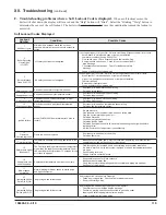
Страница 116: ...ng the Help button from the Home screen When a fault is active the Help button flashes and the home screen turns a red color Continue to select flashing buttons to be directed to the Fault cause B Dis...

Страница 117: ...etwork disconnected Sequencer Master was Enabled and then Disabled Master s Boiler has been powered down To clear fault restore communication or cycle power Boiler Size Setup Boiler Size Fault WARNING...

Страница 118: ...ere is a fault with the sensor Rate Limit Rate Limit The following messages appear when the firing rate is limited or reduced to help avoid a lockout or save energy Refer to Hard Lockout section for c...

Страница 119: ...perature sensor wiring Defective flue temperature sensor 11 Ignition failure Model PHNTM399C flame failure after 5 tries to restart No gas pressure Gas pressure under minimum value shown on rating pla...

Страница 120: ...ut 4 Boiler pump not operating Boiler pump undersized Valve closed 18 Light off rate proving failed Blower is not running at Light off rate when it should or blower speed signal not being detected by...

Страница 121: ...ctory 27 Interrupted Airflow Switch IAS ON Air proving switch failed to open Air proving switch closed before Prepurge Failed air proving switch Check switch for proper operation Short in limit string...

Страница 122: ...ts may be obtained from any Velocity Boiler Works LLC distributor To find the closest Velocity distributor consult the area Velocity representative or the factory at Velocity Boiler Works LLC Customer...

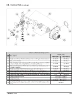
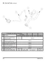
Страница 123: ...60 PSI 81660375 Alternate Safety Relief Valve Kit not shown includes safety relief valve and temperature and pressure gauge 80 PSI 104200 01 100 PSI 104201 01 1M Boiler Drain Valve 3 4 in NPT not sho...

Страница 124: ...124 106309 03 4 19 XIII Service Parts continued...

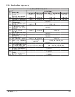
Страница 125: ...apter plate and mounting hardware 104620 04 104620 05 2E Replacement Gas Valve Kit includes one gas valve and o rings 105004 01 105004 04 2F Gas Valve 90 Flange Kit includes one 90 flange o ring and h...

Страница 126: ...126 106309 03 4 19 XIII Service Parts continued PHNTM600C PHNTM700C and PHNTM800C PHNTM800C shown...

Страница 127: ...acement Kit includes swirl plate blower adapter plate and mounting hardware N A N A N A 2E Replacement Gas Valve Kit includes one gas valve and o rings Natural Gas 105004 04 LP Gas 105004 03 2F Gas Va...

Страница 128: ...ch Kit includes float switch and clamp 105005 01 3C Spring Hose Clamp 15 16 in OD hose 101632 01 3D Rubber Grommet Condensate Trap 101595 01 3E Condensate Neutralizer Kit not shown includes limestone...

Страница 129: ...ting hardware 106508 01 4D Transformer 102516 01 103193 01 4E Replacement 120V PCB Kit includes PCB fuses and hardware 106512 01 4F Replacement Low Voltage PCB Kit includes PCB fuses and hardware 1065...

Страница 130: ...130 106309 03 4 19 XIII Service Parts continued...

Страница 131: ...nt Door Latch Kit includes latch cam and hardware 106509 01 5G Rear Panel includes gaskets 106253 01 106253 02 106253 03 5H Junction Box Access Panel 5 5 in x 10 5 in 106261 01 5J Access Panel 5 in x...

Страница 132: ...tch Wire Harness N A 106345 01 6F Flow Switch Kit not shown includes switch and paddles 106383 01 6G Flow Switch Repair Paddle Kit not shown includes paddles and hardware 106384 01 6H Outdoor Temperat...

Страница 133: ...133 106309 03 4 19 XIII Service Parts continued 10A 10B 10C 10D 10G...

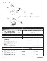
Страница 134: ...er PHNTM399C PHNTM500C PHNTM600C PHNTM700C PHNTM800C 10A 120V Harness 106003 01 10B Low Voltage Harness 106008 01 10C Fan Power Harness 103012 01 10D Ignition Harness 107211 01 10G GT02 Display Commun...

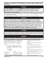
Страница 135: ...r installation at altitudes from 0 2000 ft above sea level only PHNTM399C and PHNTM500C are setup and shipped from factory as natural gas builds only For PHNTM399C or PHNTM500C conversion to LP follow...

Страница 136: ...ess than 200 ppm WARNING Asphyxiation Hazard Offset screw is adjusted at the factory DO NOT touch the offset screw if measured low fire CO2 is within limits specified in Table S2 Appendix A Instructio...

Страница 137: ...2 PHNTM500C 3 PHTNM600C N A Fatory LP Builds PHNTM700C PHNTM800C Table S1 Approximate Clockwise Throttle Screw Turns for LP Gas Propane Conversion Figure 49 Gas Valve Detail Appendix A Instructions f...

Страница 138: ...t to 7 800 ft PHNTM399C NG 8 6 9 2 2 2 LP 9 4 10 0 PHNTM500C NG 8 7 9 2 3 6 LP No Application No Application PHNTM600C NG 8 6 9 2 0 7 LP 9 4 9 7 1 2 PHNTM700C NG 8 2 8 7 0 8 LP 9 2 9 5 PHNTM800C NG No...

Страница 139: ...139 106309 03 4 19...

Страница 140: ...140 106309 03 4 19 Velocity Boiler Works LLC P O Box 14818 3633 I Street Philadelphia PA 19134 www velocityboilerworks com...

Отзывы: