23
106309-03 - 4/19
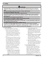
IV. Venting
B. CPVC/PVC Venting (continued)
spacing is recommended to avoid frost damage to
building surfaces where vent terminations are
placed.
q. For multiple boiler installations with vertical
roof terminals, maintain minimum 12 in.
(300 mm) horizontal distance between adjacent
boiler vent terminals.
B. CPVC/PVC Venting
WARNING
Asphyxiation Hazard. Failure to follow
these instructions could cause products of
combustion to enter the building, resulting
in severe property damage, personal injury,
or death.
Use all CPVC vent components (supplied
with boiler) for near-boiler vent piping before
transitioning to Schedule 40 PVC pipe
(ASTM 2665) components for remainder of
vent system.
Use CPVC vent components within any
interior space where air cannot circulate
freely, including through vertical or
horizontal chase ways, inside a stud wall, in
closets, and through wall penetrations.
The use of cellular core PVC (ASTM
F891), cellular core CPVC or Radel
(polyphenolsulfone) is prohibited.
All condensate that forms in the vent must
be able to drain back to the boiler.
NOTICE
Do not exceed maximum vent/combustion
air system length. Refer to “2. Vent/
Combustion Air Piping” under “A. General
Guidelines” of this section for maximum
vent/combustion air system length.
Use only vent and combustion air terminals
and terminal locations shown in “3. Vent/
Combustion Air Terminals” under “A.
General Guidelines” of this section.
1. Components
a. See Table 11 for CPVC/PVC vent and
combustion air components included with boiler.
b. See Table 12 for CPVC/PVC installer provided
vent and combustion air components required for
optional horizontal snorkel terminals shown in
Figure 8.
c. See Table 13 for installer provided Ipex Low
Profile Vent Termination Kits.
d. See Table 14 for CPVC/PVC installer provided
vent and combustion air components required for
optional vertical roof terminals shown in Figure
10.
2. Field Installation of CPVC/PP/SS Vent
Connector
Refer to Figure 12 and following steps:
a. Position the vent connector and gasket onto
boiler rear panel and insert vent connector into
heat exchanger vent outlet.
b. Align vent connector plate and gasket clearance
holes with rear panel engagement holes. Be sure
combustion sample port is on left side looking
at rear of boiler. Then, secure the connector and
gasket to the panel with four mounting screws.
3. Near-Boiler Vent/Combustion Air Piping
Refer to Figure 13 and the following Steps:
a.
Apply supplied dielectric grease to gasket inside
vent connector. The grease will prevent gasket
rupture when inserting vent pipe and gasket
deterioration due to condensate exposure.
b. Install provided Schedule 40 x 30 in. (760 mm)
long CPVC pipe into the vent section of the
connector with a slight twisting motion and
secure by tightening the clamp.
c. All CPVC vent components supplied with boiler
inside vent carton [Schedule 40 x 30 in. (760
mm) long CPVC pipe and Schedule 80 CPVC
90° Elbow] must be used for near-boiler piping
before transitioning to Schedule 40 PVC (ASTM
2665) pipe components for remainder of vent
system. The 30 in. (760 mm) long CPVC straight
pipe may be cut to accommodate desired vent
configuration provided both pieces are used
in conjunction with CPVC 90° Elbow before
any PVC components are used. Ensure that the
CPVC 90° Elbow is the first elbow used in the
vent system as it exits the boiler.
d. Apply PVC primer and cement and insert
Schedule 40 PVC combustion air pipe (installer
provided) into the combustion air connector with
a slight twisting motion.
4. System Assembly
WARNING
Asphyxiation Hazard. CPVC/PVC vent piping and
fittings rely on glued joints for proper sealing.
Follow all manufacturer instructions and
warnings when preparing pipe ends for joining
and using the primer and the cement.
Содержание Phantom-X Series
Страница 15: ...15 106309 03 4 19 III Pre Installation and Boiler Mounting H Boiler Stacking continued Figure 5 Boiler Stacking...
Страница 49: ...49 106309 03 4 19 VI Water Piping and Trim continued Figure 28 Near Boiler Piping Heating Only...
Страница 63: ...63 106309 03 4 19 VIII Electrical continued Figure 40 Ladder Diagram...
Страница 64: ...64 106309 03 4 19 VIII Electrical continued Figure 41 Wiring Connections Diagram 2...
Страница 73: ...73 106309 03 4 19 IX System Start up continued Figure 47 Operating Instructions...
Страница 124: ...124 106309 03 4 19 XIII Service Parts continued...
Страница 126: ...126 106309 03 4 19 XIII Service Parts continued PHNTM600C PHNTM700C and PHNTM800C PHNTM800C shown...
Страница 130: ...130 106309 03 4 19 XIII Service Parts continued...
Страница 133: ...133 106309 03 4 19 XIII Service Parts continued 10A 10B 10C 10D 10G...
Страница 139: ...139 106309 03 4 19...


