


(If the set temperature is more than or equal to 200
℃
) or 50
℃
(If the set temperature is less
than 200
℃
) and remain the temperature until resuming the unit.
To resume soldering , there are several ways as follows:
1.
Turn the power switch OFF , then ON.
2.
Hit any button.
3.
Take up the iron
——
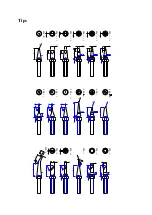
Hand Assembly
If the unit is not resumed more than 40 minutes after it comes to sleep, the power supply will
be shut off automatically, and the display window will not show anything.
SECTION 13 Temperature Calibration
The Soldering Iron’s temperature should be recalibrated after replacing the iron or heating
element or nozzle every time. The unit adopts digital calibration mode and the revision value
is input by pressing button to make the adjustment simply and quickly.
Method of recalibrating temperature: Use the thermometer to calibrate , and it is precise
comparatively.
Calibrate by using thermometer
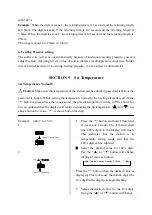
1.
Set the unit’s temperature to a certain value.
2.
When the temperature stabilizes, measure the tip’s temperature with thermometer and
write down the reading.
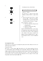
3.
Press
“*”
button not loose and press the
“▲”
and
“▼”
button simultaneously, the
unit enters into calibrating temperature mode.
4.
At the moment, the 100’s digit of LED display temperature is flashing. Press the
“▲”
and
“▼”
button to select the value and press
“*”
button to select the digit. Input the reading
of thermometer, and inputting method is the same as
Set temperature normally
. Press
“*”
button after inputting. Here, the whole calibration operation has been finished.
5.
If the temperature still has deflection, you can repeat calibration in accordance with above
steps.
* We recommend to use the 191/192 thermometer for measuring the tip temperature.
* If the unit is locked by password, it will not be able to calibrate the nozzle temperature
and you must input the right password.
SECTION 14 Operation
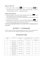
Do corresponding operations in accordance with the chosen Feeding Mode.
Manual:
(The Mode switch is set as 0)
Turn on power switch and LED window display temperature, the unit is in working state. Step
on Pedal Switch or press the red Touch Switch, and the unit works. After loosing it, returning
once and then stop working. Feeding Length and Feeding Interval and Feeding Mode are all


