background image

5. Installing the Equipment: Wall Mount 
 

68 

PaX-i Plus / Insight Installation Manual 

Combining the Equipment with the Anchor Bolts 

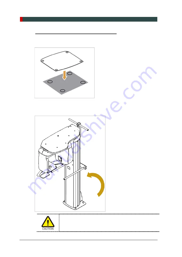
1. 

Put  the  align  plate  on  the  floor  while  making sure that the align plate’s holes engage 
in the anchored bolts. 


2. 

Put the equipment in a vertical position  slowly while holding the upper handle as 
shown  in the figure. 


Be careful not to damage the cables  before erecting the equipment. 
Keep them clear  of the equipment. 

Содержание PaX-i Insight

Страница 1: ......

Страница 2: ......

Страница 3: ......

Страница 4: ......

Страница 5: ... and the equipment described herein This IPR is protected by related laws and reproduction of this manual in part or in full is prohibited without the prior written consent of the Manufacturer This Equipment is covered by one or more of the patents and published patent applications including US8634515 US9117301 US9486174 KR1032963 KR1021847 KR1389841 KR1664166 EP2851004 US2017027536 KR20170063689 ...

Страница 6: ... a flat surface to maintain stability If the equipment is not stable property damage and or personal injury may occur Do not push or pull the equipment Equipment should only be installed by an authorized technician complying with proper installation procedures Failure to read and understand the information provided in this manual may result in physical injury damage to the equipment or equipment f...

Страница 7: ...nstalling the Warning Lamp and Door Interlock Switch 22 2 8 Installing the Emergency Stop Switch 22 3 Before Installing the System 23 3 1 Required Tools 23 3 2 Checking the ShockWatch and TiltWatch Indicators 25 3 3 Unpacking Boxes 26 3 4 Checking the Parts 33 4 Installing the Equipment Base Stand Optional 39 4 1 Unloading the Base and Main Unit 39 4 2 Assembling the Base with the Column Unit 42 4...

Страница 8: ...rnal Peripherals 83 7 4 Connecting the Cables to PC 85 8 Setting up PC s Environment Variables 87 8 1 Before Beginning 87 8 2 Turning off the Firewall 89 8 3 Setting up the Power Mangement Options 90 8 4 Turning off the User Account Control 92 8 5 Setting Folder Exclusions with Anti virus Software 93 9 Installing Software 95 9 1 Before Beginning 95 9 2 Software Installation Flow 96 9 3 Installing ...

Страница 9: ...Table of Contents PaX i Plus Insight Installation Manual v E Checking PC BIOS Settings 132 F Installation Checklist 133 ...

Страница 10: ...Table of Contents vi PaX i Plus Insight Installation Manual ...

Страница 11: ... accordance with the user s manual PC Software has been properly used in accordance with the manufacturer s installation instructions and user manuals 1 2 Customer s Responsibility Site planning and preparation are the responsibility of the customer The following points should beconsidered fundamentally important to all customers of thisproduct Install all required materials prior to delivery of t...

Страница 12: ...dicates information that should be followed with the utmost care Failure to comply with a warning may result in severe damage to the equipment or physical injury to the operator and or patient CAUTION Indicates a situation that demands prompt and careful action a specific remedy or emergency attention IMPORTANT Indicates a situation or action that could potentially cause problems to the equipment ...

Страница 13: ...ch or hold the Sensor or Tube Head areas while moving installing or operating the equipment Do not use the electrical power drill during installation unless it is allowed to do so Do not use the electrical power drill during installation unless it is allowed to do so ...

Страница 14: ...llation Manual Recommended holding area during transportation is as below Three installers are required to install the equipment safely The Main Power Switch and Emergency Stop Switch are located under the bottom of the Vertical Frame as below ...

Страница 15: ...1 1 3rd edition 2005 Any equipment not approved by VATECH must comply with the applicable standards IEC 60950 1 2nd edition 2005 for IT equipment Ex PC and IEC 60601 1 3rd edition 2005 for medical electrical equipment All operators of this equipment are responsible for ensuring that the requirements outlined in IEC 60601 1 1 3rd edition 2005 Safety Requirements for Medical Electrical Equipment are...

Страница 16: ...ements for electro medical systems IEC 60364 7 710 2002 It is strongly recommended that a UPS be installed at the same time as the equipment The equipment PC and all peripheral devices must be well grounded Warnings Regarding X ray Radiation Failure to install this equipment in an approved location may be dangerous to the patient and operator Stationary radiation shielding must be installed to pro...

Страница 17: ...pment IEC60601 2 7 and IEC60601 2 28 X ray Tube Heads IEC60364 7 710 2002 Local Code Requirements for Electro medical System Installation IEC 60601 1 1 2005 regulation shall be met to their full extent for the safety of the patients operators and the environment when any person assemble or modify a medical electrical system by combing it with other equipment Any equipment not provided by VATECH ca...

Страница 18: ...rrent Label Type B Applied Equipment IEC 60601 1 Degree of protection against leakage current and or electric shock Class 1 equipment Label Radiation hazard Label Indicates the authorized representative in the European Community Label The CE symbol indicates that this product complies with the European Directive for Medical Devices 93 42 EEC as amended by 2007 47 EC as a class IIb device Label CSA...

Страница 19: ...unicipal waste and must be collected separately Label Warns ESD hazard MCU board Board package Indicates that this equipment is classified as a CLASS 1 LASER PRODUCT in accordance with IEC 60825 1 ED 2 regulations Label Indicates that the user needs to refer to the Instruction Manual Label Indicates the date of manufacture Label Indicates the manufacturer s serial number so that the specific equip...

Страница 20: ...I ES60601 1 2005 R 2012 AND A1 2012 A2 2010 R 2012 Consolidated text edition 3 1 21 CFR 1020 30 31 33 NEMA Standard publication PS 3 1 3 18 2008 This is Class IIb equipment and obtained CE marking in April 2007 for regulations compliance in accordance with the revised European Union s MDD Medical Devices Directive 93 42 EEC This equipment received the CSA certification mark in accordance with CAN ...

Страница 21: ... by the operator and the operator should be as near to the patient as possible This equipment should not be installed on thick carpets for stability reasons Anti static floor materials should be used around the equipment The PC monitor emergency cut off switch and X ray Exposure Switch should be installed in the vicinity of the operator so that he or she can manage them simultaneously in case of e...

Страница 22: ...2 Choosing an Installation Site 12 PaX i Plus Insight Installation Manual Without CEPH Unit optional 2 200 mm L x 1 400 mm W or wider ...

Страница 23: ...2 Choosing an Installation Site PaX i Plus Insight Installation Manual 13 With CEPH Unit optional 2 200 L x 2 200 mm W or wider Ceiling Height 2 600 mm H or higher ...

Страница 24: ...rance The door of the X ray room should have a clearance of more than 800 mm 31 5 wide Floor Area The floor of the X ray room must be stable and level for system balance The floor must be able to support a minimum weight of 500 kg m 2 110 lbs feet 2 Protection against Radiation To protect against radiation hazards follow all federal and municipal requirements During exposure the operator should fo...

Страница 25: ...to the same MPSO Use a dedicated power outlet for the power cord Failure to do so may result in unstable system operation caused by power fluctuations It is strongly recommended that you install an AVR An AVR automatic voltage regulator maintains a constant voltage and allows for continuous operation in the event of a power fluctuation Item Description Power supply voltage 100 240 V Frequency 50 6...

Страница 26: ...tribution panel with over current circuit breaker rated for 20A must be used Maximally allowed deviation of the tube voltage tube current exposure time Tube Voltage kVp 10 Tube Current mA 20 Exposure Time s 5 50 ms according to IEC 60601 2 63 The mains resistance should not exceed 0 045 ohm at 100 V and 0 19 ohm at 240 V This equipment should be connected to the earthed outlet ...

Страница 27: ...ion Manual 17 2 4 Environmental Specifications Item Description During Operation Temperature 10 35 Relative humidity 30 75 Atmospheric pressure 860 1060 hPa During Transport and Storage Temperature 10 60 Relative humidity 10 75 Atmospheric pressure 860 1060 hPa ...

Страница 28: ...are three options for installation depending on the configuration of the site Nevertheless the 2nd option is preferred Option No 1 The user operates the Exposure Switch from inside the X ray room Option No 2 The user operates the Exposure Switch from outside the X ray room The Exposure Switch holder is mounted on the wall ...

Страница 29: ...ite PaX i Plus Insight Installation Manual 19 Option No 3 The 3rd party Exposure Switch not VATECH s is used on demand of the customers For this scenario see the Appendix D Connecting the 3rd party The Exposure Switch for details ...

Страница 30: ...2 Choosing an Installation Site 20 PaX i Plus Insight Installation Manual 2 6 Installation Versions Base stand Type ...

Страница 31: ...2 Choosing an Installation Site PaX i Plus Insight Installation Manual 21 Wall mount Type ...

Страница 32: ...rgized The warning lamp and Door Interlock Switch are not included with the equipment The warning lamp and the Door Interlock Switch must be installed by a qualified technician 2 8 Installing the Emergency Stop Switch Refer to Appendix B for a complete installation guide Install the Emergency Stop Switch along the main power cable in the central distribution panel Install this switch so that it is...

Страница 33: ...st No 3 through No 6 in the Appendix F Installation Checklist 3 1 Required Tools The following tools are necessary to install the PaX i Plus Insight Item Figure Size Wrench Set 1 5 mm 10 mm 0 06 0 4 T shaped Hex Wrench 6 mm 10 mm 0 24 0 4 Hex Wrench w Handle 6 mm 10 mm 0 24 0 4 Ratchet Wrench Tips 3 mm 8 mm 0 12 0 3 Needle nose Pliers Regular Monkey Wrench n a Spanner Wrench n a ...

Страница 34: ...Cross Head Screw Driver w Magnetic Tip L 200 mm 7 9 Spirit Level n a Anti Static Glove n a Knife n a Tape Ruler for Wall Mount type 5 m Marker Pen thick tip for Wall Mount type n a Hammer for Wall Mount type n a Multimeter n a Hammer Drill for Wall Mount type L 200 mm 7 9 Transport Dolly n a ...

Страница 35: ... package has suffered any physical impacts during transportation However a red indicator does not necessarily mean that the unit has been damaged These indicators are affixed only on the main box which contains the equipment very sensitive to external impacts Check the followings before opening each package 1 These indicators are affixed only on the main box which contains the equipment very sensi...

Страница 36: ... is recyclable Return the packaging to VATECH representatives or dispose of it in compliance with the legal regulations of your country 3 3 1 Box No 1 Main Box Component Size mm inch Weight kg lbs Column and Rotating Unit Assembly Accessories and Parts PC System Optional Monitor Optional 1 710 L x 680 W x 1 100 H 67 L x 27 W x 43 H 145 320 Main Box ...

Страница 37: ...g the Cover 1 Move the Main Box to a convenient place as close as possible to the installation location 2 Remove the Top Cover 3 Remove a single side cover In case of unabling to lift the side cover up fully due to ceiling height cut the box in half using the utility knife instead ...

Страница 38: ...C System Optional down on the floor 5 Separate two side EPS A B The resulting view is as follows Do not discard thease EPS A B so that they are reused later when the CEPH unit is installed 6 Separate two side EPS A B The resulting view is as follows 7 Remove the case column front cover ...

Страница 39: ...3 Before Installing the System PaX i Plus Insight Installation Manual 29 The view after removal of the EPS is as below ...

Страница 40: ...tem 30 PaX i Plus Insight Installation Manual 3 3 2 Box No 2 Base Unit Component Size mm inch Weight kg lbs Base 1046 L x 1056 W x 185 H 41 L x 41 5 W x7 H 47 103 Removing the cover 1 Open the box cover the Base Cover is appeared ...

Страница 41: ...3 Before Installing the System PaX i Plus Insight Installation Manual 31 2 Remove the upper box the Base Unit is appeared ...

Страница 42: ...ht Installation Manual 3 3 3 Box No 3 CEPH Unit Optional Component Size mm inch Weight kg lbs CEPH unit 1590 L x 820 W x 870 H 62 6 L x 32 3 W x34 3 H 50 110 Removing the cover 1 Open the box cover and remove the packing material as shown in the figure ...

Страница 43: ...3 Before Installing the System PaX i Plus Insight Installation Manual 33 3 4 Checking the Parts 3 4 1 Location Layout of the Parts and Accessories ...

Страница 44: ...ed OK 1 Manuals User Manual 1 Yes No Installation Manual 1 Yes No 2D Viewer Manual 1 Yes No Installation CD 1 Yes No USB Key 2D Viewer key 1 Yes No 2 Exposure Switch 1 Yes No Exposure Switch Holder 1 Yes No UP DOWN Switch Holder 1 Yes No Double Sided Sticker 1 Yes No Screws M3X16 3 Yes No 3 Hand Plate Carpus 1 Yes No Handrest Sticker 1 Yes No 4 Plate Align Wall 1 Yes No ...

Страница 45: ...oves 1 pair Yes No 7 Chin Block_High ABS WHITE 1 Yes No 8 CHIN_BITE PC transparent Black 1 Yes No CHIN BITE2 PC transparent Black 1 Yes No 9 Left Blank Intentionally 10 SINUS Bite 1 Yes No 11 PANO Cover Box PP BAG 1 Yes No 12 Left Blank Intentionally 13 Left Blank Intentionally 14 Cap For Ear Rods 2 2 CEPH Option 2 on the equipment Yes No Silicon Cover For Nasal Positioner 1 CEPH Option extra Yes ...

Страница 46: ...lank Intentionally 19 Left Blank Intentionally 20 Cable Tie 10 Yes No 21 Frame Grabber System Optic Cable 1 One additional fiber optic cable is required when Yes No IFC Card 1 Yes No 22 Wall Bracket 2 1 Yes No Protractor 1 Yes No 23 Wrench Bolt M10 x 20 w Spring 4 Yes No 24 Wrench Bolt M10 x 25 w Spring and Flat Washers 2 Yes No Wrench Bolt M10 x 25 2 Yes No 25 Wrench Bolt M8 x 45 w Spring and Fla...

Страница 47: ...000009 1 For domestic only Yes No 29 Wrench Bolt M8 x 20 w Spring and Flat Washers 4 Yes No 30 Set Screw M10 x 20 4 Yes No 31 Wall Plate 1 Yes No Terminal Blocl 3 Pole 1 Yes No 32 Left Blank Intentionally 33 UP DOWN Switch 1 Yes No UP DOWN Switch Holder 1 Yes No Double Sided Sticker 1 Yes No 34 Ficher strong anchor M10X40 EAM8N 4 column Yes No Wrench Bolt M10_L20 W Spring Washer 4 Yes No Ficher st...

Страница 48: ...re QTY Comments Confirmed OK Hex Bolt M8_L15 W Spring Washer 4 Yes No Wood Screw M8 x 60 4 wall Wood Yes No Wood Screw M12 x 70 2 base Yes No Wrench Bolt M8 x 25 w Spring and Flat Washers 2 wall Bracket Yes No Nut M8 2 wall Bracket Yes No 35 Wall Bracket 1 1 Yes No Wall Bracket 2 1 For Americal only Yes No ...

Страница 49: ... the Equipment Base Stand Optional 4 1 Unloading the Base and Main Unit 1 First unload the Main Unit on the floor Place some protective stuff on the floor to avoid the scratches on the surface One installer should keep on holding the Vertical Frame area to keep the equipment stable after it is unloaded ...

Страница 50: ... the Main Unit back on the master packing EPS and remove the protective plastic cover with knife Then put the cables down on the floor carefully Be careful not to damage the cables or have the column surface scratched 3 Assemble two wrench bolts as shown as below Wrench Bolt M10 x 25 Part No 24 ...

Страница 51: ...4 Installing the Equipment Base Stand Optional PaX i Plus Insight Installation Manual 41 4 Remove the carrying handle at the bottom of the column unit Allen Wrench 6 mm 0 24 ...

Страница 52: ...n Unit If the installation site is a concrete floor go to the section 4 5 Fixing the base Optional and do number 1 first after that turn back 4 2 Assembling the Base with the Column Unit 1 Hang the base unit onto two bolts temporarily as shown as shown as below An installer should hold the base unit to keep it from falling down ...

Страница 53: ...us Insight Installation Manual 43 2 Fasten the Base Unit with two Wrench Bolts Allen Wrench 8 mm 0 3 Wrench Bolt M10 x 20 w Spring Part No 23 Put the bolts into the holes until about 20 mm are left outside 3 Tighten two Wrench Bolts firmly as shown as below ...

Страница 54: ...ut the equipment in a vertical position slowly while holding the upper handle Be sure not to damage the cables Before erecting the equipment keep them clear of the equipment 5 Tighten the three Wrench Bolts to attach the base unit Allen Wrench 8 mm 0 31 Wrench Bolt M10 x 20 w Spring Part No 23 ...

Страница 55: ...ional PaX i Plus Insight Installation Manual 45 4 3 Removing the Transportation Handle without the CEPH unit 1 Remove the upper carrying handles Allen Wrench 6 mm 0 24 One installer should hold the handle while the other is removing the bolts ...

Страница 56: ...n Brackets Assembling the Column Bracket 1 Remove the plastic wrap covering the column unit by using a cutter 2 Prepare the column bracket Wall Bracket 2 Part No 22 3 Attach the above bracket to the back of the column with the four Wrench Bolts Wrench Bolt M8 x 20 w spring and flat washers Part No 29 Allen Wrench 6 mm 0 24 ...

Страница 57: ... and Wall Brackets 1 Prepare the wall bracket Wall Bracket Part No 35 2 Combine the column and wall brackets in the following manner with the 2 Wrench Bolts Allen Wrench 6 mm 0 24 Wrench Bolt M8 x 25 w Spring and Flat Washers Part No 34 Monkey Wrench n a Nut M8 Part No 34 Do not tighten the bolts fully yet ...

Страница 58: ...ion Manual Martking Points on the Wall 1 Move the equipment to the installation site as close as possible 2 Adjust the distance between the wall and equipment by moving it slightly so that the wall bracket touches the wall 3 Mark four anchor bolt locations on the wall Marker n a ...

Страница 59: ...al 49 Drilling on the Wall 1 Drill the wall holes of size 10 5 mm x 30 mm depth using the concrete hammer drill 2 Remove the debris and clean the holes using the dust pump 3 Using the hammer insert a Ficher strong anchor into the hole Ficher strong anchor M8 x 30 Part No 34 Hammer n a ...

Страница 60: ...ts positionand and fix the wall bracket to the wall with four Hex Bolt Part No 34 Hex Bolt M8_L15 W Spring Washer Part No 34 Sapanner Wrench n a Allen Wrench 6 mm 0 24 2 Remove the middle carrying handle If the CEPH unit is to be installed this is used as the carrying handle Do not detach it until indicated later after the equipment is moved to the installation site ...

Страница 61: ...g the Transportation Safety Bolts 1 Remove the semi transparent tape on both sides of the vertical top cover When removing the semi transparent tape be careful not to scratch the surface of the equipment 2 Remove the vertical top cover 3 Remove the safety lock bolt with a wrench Allen Wrench 6 mm 0 23 ...

Страница 62: ...er hold the areas of the collimator sensor and tube head 1 Now it is assumed that the CEPH box has already been opened 2 Remove the plastic wrap covering the column unit and the tape for fixing the CEPH cables by using a cutter 3 Move and mount the CEPH unit on the Main Unit carefully while observing the insertion state of 4 studs ...

Страница 63: ...attach the base unit Allen Wrench 6 mm 0 24 Wrench Bolt M8 x 45 w Spring and Flat Washers Part No 25 When fastening a bolt make sure that the cable is not stuck on the surface When removing the semi transparent tape be careful not to scratch the surface of the equipment 5 Connect the cable between the CEPH unit and main unit ...

Страница 64: ...board 7 Connect the H002040A fiber optic cable to the CEPH port of the optic hub When handling fiber optic cable Do not bend pull and or crushing it Ensure that the caps of the fiber optic cable be removed Do not touch the tip of the fiber optic cable to prevent it from being dirty Insert the fiber optic cable fully until the click sound is heard ...

Страница 65: ...icher strong anchor M10 x 40 Part No 34 Allen Wrench 8 mm 0 3 Wrench Bolt M10 x 25 w Spring and Flat Washers Part No 24 1 Before installing the equipment put the base unit on the installation site and mark 2 locations on the floor 2 Drill the floor holes of size 12mm x 30mm depth using the concrete hammer drill 3 Remove the debris and clean the holes using the dust pump ...

Страница 66: ...ipment Base Stand Optional 56 PaX i Plus Insight Installation Manual 5 Secure the anchor bolts with the hammer 6 Place the base unit combined equipment on the proper position lock the nuts and washers using ratchet wrench ...

Страница 67: ...4 Installing the Equipment Base Stand Optional PaX i Plus Insight Installation Manual 57 Wooden Floor Wood Screws M12 x 70 Part No 34 Hammer Drill L 200 mm 7 9 Secure the base unit using the wood screws ...

Страница 68: ... Stand Optional 58 PaX i Plus Insight Installation Manual 4 8 Connecting the Cables to the Equipment 1 Connect the cables in the back of the column as shown in the figure Optic Cable Cable No H002040A Part No 21 Cable Tie Part No 20 ...

Страница 69: ...alling the Equipment Base Stand Optional PaX i Plus Insight Installation Manual 59 2 Use the Cable Tie Part No 20 or Cable Holder Part No 20 to fix the cables as shown below after the connection is completed ...

Страница 70: ...sure that the Spirit Level should restonly on the locations indicated in the following figures to obtain the accurate center 1 Prepare the Spirit Level 2 Turn the Rotating Unit clockwise so that the X ray tube head faces the front as shown in the figure 3 Remove the case column front 4 Turn all screws on the base plate unit clockwise until they touch the ground ...

Страница 71: ... PaX i Plus Insight Installation Manual 61 Leveling Right and Left 1 Place the Spirit Level as shown in the figure 2 Adjust the base until the bubble on the Spirit Level centers in the middle by turning left and right screws clockwise or vice versa ...

Страница 72: ...l Frame as shown in the following figure 2 Adjust the screws until bubble of Spirit Level centers level by turning the front and or back screws clockwise or vice versa 3 When the leveling is completed make sure that all eight set screws touch the floor by turning them clockwise if necessary 4 Assemble the vertical top cover 5 Assemble the case column front ...

Страница 73: ...4 Installing the Equipment Base Stand Optional PaX i Plus Insight Installation Manual 63 4 10 Tightening the Bolts 1 Tighten the joint bracketbolts Allen Wrench 6 mm 0 24 Monkey Wrench n a ...

Страница 74: ...4 Installing the Equipment Base Stand Optional 64 PaX i Plus Insight Installation Manual This page intentionally left blank ...

Страница 75: ...e Equipmet You are advised to plan and study the installation environment carefully in advance before proceeding since the installation involves drilling the wall and floor Pre installation planning is crucial to a successful installation An accurate marking is of critical importance for a successful installation Installation Overview ...

Страница 76: ...lus Insight Installation Manual Marking Points on the Floor 1 Put the align plate on the floor near the wall where the equipment should be installed as shown in the figure Alignmnet Plate Part No 4 2 Mark 6 anchor bolts holes on the floor Marker n a ...

Страница 77: ...ll the floor holes size 10 5 x 30 mm by using the concrete hammer drill 3 Remove the debris and clean the holes withthe dust pump 4 Put the Ficher strong anchor bolts into the holes and attach them with the hammer Verify that the Ficher strong anchor s are secured Ficher strong anchor M10 x 40 Part No 34 Hammer Drill L 200 mm 7 9 ...

Страница 78: ... Bolts 1 Put the align plate on the floor while making sure that the align plate s holes engage in the anchored bolts 2 Put the equipment in a vertical position slowly while holding the upper handle as shown in the figure Be careful not to damage the cables before erecting the equipment Keep them clear of the equipment ...

Страница 79: ...washers and nuts into the six anchored bolts on the floor and tighten the nuts loosely Make sure that you put the fasteners in the sequence as shown in the figure Allen Wrench 8 mm 0 3 Wrench Bolt M10 x 20 w Spring Part No 23 Do not tighten the nuts until the leveling is completed While one installer is tightening the nuts the other installers should hold the middle handle to prevent the equipment...

Страница 80: ...ll and Column Brackets Please refer to the section 4 4 Installing the Wall and Column Brackets 5 4 Removing the Transportation Safety Bolts Please refer to the section 4 5 Removing the Transportation Safety Bolts 5 5 Installing the CEPH Unit Optional Please refer to the section 4 6 Installing the CEPH Unit Optional 5 6 Connecting the Cables to the Equipment Please refer to the section 4 8 Connecti...

Страница 81: ...x Wench 8 mm 0 3 Sprit Level n a Ensure that the Spirit Level should restonly on the locations indicated in the following figures to obtain the accurate center 1 Prepare the Spirit Level 2 Turn the Rotating Unit clockwise so that the X ray tube head faces the front as shown in the figure 3 Remove the column front case ...

Страница 82: ...on Manual 4 Put the set screws into the four holes and turn them clockwise with the hex wrench until they touch the align plate T shaped Hex Wench 8 mm 0 3 Set Screw M10 x 20 Part No 30 5 Put the Spirit Level on the location as shown in the figure Leveling Right and Left ...

Страница 83: ...sight Installation Manual 73 Leveling the Front and Back 6 Assemble the vertical top cover 7 Turn each set screw clockwise or counterclockwise to make the equipment level while another person monitors the level indicator 8 Assemble the column front case ...

Страница 84: ...nt Wall Mount 74 PaX i Plus Insight Installation Manual 5 9 Tightening the Bolts 1 Tighten the joint bracketbolts Allen Wrench 6 mm 0 24 Monkey Wrench n a Allen Wrench 8 mm 2 Tighten the nuts in the anchored bolts on the floor ...

Страница 85: ...aneous Works 6 1 Assembling Base Cover Optional When removing the semi transparent tape be careful not to scratch the surface of the equipment 1 Assemble the base cover Base Cover 2 Fix the base cover with 3 truss bolts Truss Bolt M5 x 8 Part No 26 Cross Head Screw Driver w Magnetic Tip 6 mm 0 24 ...

Страница 86: ...6 Completing Miscellaneous Works 76 PaX i Plus Insight Installation Manual 3 Cover the holes Cap1 3 Cap2 6 Base Caps 1 Part No 17 Base Caps 2 Part No 17 ...

Страница 87: ...ssembling the Temple Supports and the Bite Block should be done after Acquiring a test image is completed 1 Insert the normal Chinrest and the normal Bite Block into the unit Chin Block_High Part No 7 Chin_Bite Part No 8 Chin Bite2 Part No 8 2 Insert the Temple Supports Temple Supports 1 set Part No 5 Cap Ear ROD 1 set Part No 5 ...

Страница 88: ...X16 Part No 2 UP DOWN Switch Holder 1 Peel out the papers of the double sided sticker 2 Attach the switch support to a suitable height on the left of the column Exposure Switch Holder 1 Locate the Exposure Switch Holder with a sticker and three screws 2 Install the Exposure Switch Holder on the wall at the appropriate height using three screws UP DOWN Switch When installation of the Up Down switch...

Страница 89: ...ght Installation Manual 79 7 Setting up PC 7 1 Direct Connection Diagram Fiber Optic Cable Used to transfer image data to thePC Warning System Panel Used to provide a visible indicator Light on when the equipment is irradiating X ray ...

Страница 90: ...y it is strongly recommended to use the AVR automatic voltage regulator in order to keep the line voltage stable The PC system provided with the PaX i Plus Insight undergoes the rigorous test for software compatibility before shipping Therefore any later changes to the hardware and or software may cause malfunction Item Specification HP CPU Intel Core i3 6100 3 7G 3M 2133 2C CPU RAM 4GB DDR4 2133 ...

Страница 91: ...D G2 Chassis In Windows 10 disable Windows Defender When Windows Defender is not enabled Windows 10 is not protected from malware and virus Disabling Windows Defender 1 Open the Start screen type Windows Defender in the search box 2 Click the Windows Defender icon to start Windows Defender on the search result 3 Click Settings icon 4 On the Settings window click Add an exclusion in Exclusions sect...

Страница 92: ...7 Setting up PC 82 PaX i Plus Insight Installation Manual 5 On Select Folder window type C VcaptureSW in the folder field and and click Exclude this folder ...

Страница 93: ...er cord from the main outlet or PC Disregard this section in case the PC system is supplied with the equipment The peripherals have already been installed inside the PC Whenever handling the fiber optic frame grabber board 1 Wear the ant static glove 2 Do not wear the likes of a thick jacket The following figures and descriptions are based on the PC model Z440 from HP ...

Страница 94: ...n the PC cover 3 Insert the fiber grabber board Part No 21 carefully into that PCIe2 x 4 slot and lock it Double check the locking status between the board and its holder after the board installed A bad insertion of the board into the PC slot could cause failure for Dark calibration data acquisition or noisy image acquisition 4 Put the slot holder back to its initial position ...

Страница 95: ...se from the bad cable or its bad contact condition Connect the regular cables for PC keyboard mouse and video in advance The following figures and descriptions are based on the PC model Z440 from HP Fiber Optic Cable Part No 21 3D Viewer License Key Part No 1 1 Remove the caps of the fiber optic cable 2 Connect the Fiber Optic Cable 3 Insert the 3D viewer 3D Viewer License Key into a USB port ...

Страница 96: ...7 Setting up PC 86 PaX i Plus Insight Installation Manual 4 Confirm the the end result after connections is as same as below The illustrations may differ from the actual product ...

Страница 97: ...C server for image management it is strongly recommended to use a different PC The programs related to acquisition viewing and manInsert the 3D viewer USBipulation of images should be installed on the formatted PC where no other program s except the operating system OS is present Before InstallPakage installation ensure that the video card driver installed on PC is the most up to date version To c...

Страница 98: ...default Main Menu Sub1 Menu Sub2 Menu Setup Value Advanced Power Options Runtime Power Management Disable Advanced Power Options Idle Power Savings Normal Advanced Power Options Enhanced Halt State C1E Disable When you update the BIOS settings EnhancedHalt State C1E option will be displayed ...

Страница 99: ...ion For this reason it is required to disable the Windows Firewall by using the following procedures 1 Open the Start screen type Windows Firewall in the search box 2 Click the Windows Firewall icon to start Windows Firewall on the search result 3 On Windows Firewall screen click the Turn Windows Firewall on or off 4 Select the Turn off Windows Firewall for both Home or work private and Public net...

Страница 100: ...o avoid disruptive and abnormal operation while acquiring image it is required to reconfigure some parameters on the Windows operating system Disable the Screen Saver 1 Open the Start screen type Screen Saver in the search box 2 On Screen Saver Settings screen select None in the pull down menu 3 Click OK to apply the settings ...

Страница 101: ... 91 Selecting the Power Options Monitor and System 1 Open the Start screen type Power Options in the search box 2 Click Choose when to turn off the display 3 Select Never for both Turn off the display and Put the computer to sleep fields 4 Click Save changes to apply the settings ...

Страница 102: ...us Insight Installation Manual 8 4 Turning off the User Account Control 1 Open the Start screen type User Account Control in the search box 2 Disable the UAC by moving the slider bar down to the bottom Never notify Then click OK to apply change settings ...

Страница 103: ...ns performed by the anti virus software For the PaX i Plus Insight the following folders and files inside for relevant softwares should be excluded with the virus scan Path Software C ProgramFiles Vatech EzDent i C VCaptureSW Console Software Suppose the anti virus program from McAfee is running in the background The procedure to set folder exclusions is similar for most anti virus programs 1 Open...

Страница 104: ...8 Setting up PC s Environment Variables 94 PaX i Plus Insight Installation Manual This page intentionally left blank ...

Страница 105: ...on the same PC There may be subtle conflicts between them leading to the malfunction The image viewer program such as EzDent i or the one from the 3rd party should be installed in advance before the InstallPakage installation For the information on their installation procedures refer to the corresponding manuals Before InstallPakage installation ensure that the video card driver installed on the P...

Страница 106: ...n Manual 9 2 Software Installation Flow 9 3 Installing Image Viewer Program One of the image viewer programs among EzDent i or 3rd party program must be installed at this time For the details on the installation procedures refer to the corresponding manuals ...

Страница 107: ... in the CD case The sensor type PANO and CEPH if installed of the equipment is checked in the this manual 1 Turn on the PC and the equipment if they are not yet 2 Insert the CD into the CD ROM drive and then perform virus scan for the PC before installing the CD 3 Go to the InstallPakage folder and run Setup exe 4 The following screen will appear Click Next ...

Страница 108: ...nd then click Next 8 Optional Confirm that the WideCeph is selected in CEPH sensor type selection window and click Next 9 Select COM2 for the default port number and click Next 10 Select the language and click Next 11 Select the 3rd party software in use and click Next when EzDent i is installed select SDK Then click Next to continue EzDent i 12 Check the options according to the product specifica...

Страница 109: ... Plus Insight Installation Manual 99 14 You can check the information entered so far with the Ready to Install window If necessary you can modify it by clicking Back 15 When the information is confirmed click Install to continue ...

Страница 110: ...ng Software 100 PaX i Plus Insight Installation Manual Installing the DirectX 1 After completing DICOM viewer installation DirectX installation will be started Select I accept the agreement in the Welcome window ...

Страница 111: ...9 Installing Software PaX i Plus Insight Installation Manual 101 2 Click Next to start installation ...

Страница 112: ...9 Installing Software 102 PaX i Plus Insight Installation Manual 3 Click Finish to exit the wizard ...

Страница 113: ...lling the Frame Grabber Virtual Serial 1 x 1 After completing Direct X installation Virtual Serial 1 x installation will be started Click Install in the Welcome window 2 During installation VA_4x Cap 1 x installation wizard will appear Click Install to start installation ...

Страница 114: ... Microsoft Visual C 2010 x64 Redistributable installation window appears click Install to continue the process and click Finish when completed 6 Optional When Microsoft NET Framework 4 x x installation window appears click Install to continue the process and click Finish when completed 7 When the Vitual Serial 1 x installation is completed click Finish to exit the wizard ...

Страница 115: ...tall_Log txt on the desktop 2 Open it to check the file You can find out that all components are installed 3 Go to the section 9 5 Setting up the User specific Information Uninstalling Software 1 Open the Start screen type Uninstall a Program in the search box 2 Find the programs you want to uninstall and double click the program to uninstall 3 When you are asked if you want to continue click Yes ...

Страница 116: ... corresponding section for set up instructions based on the viewer program EzDent i SDK installed on PC EzDent i Refer to section 9 5 1 when EzDent i is installed 9 5 1 When EzDent i is installed Running the Image Viewer 1 Run the image viewer On your desktop double click EzDent i icon Its main window will be displayed ...

Страница 117: ...n of EzDent i click EzDent i Setting 2 Click Acquisition Console Program 3 Make sure that the console program settings are as follows Console Program Path C VCaptureSW exe VCaptureSW exe Capture Message PaX i Plus_Insight Captured Patient Information File Path C VCaptureSW PatientInfo ini 4 Click OK and restart the program to apply the settings ...

Страница 118: ...ct refer to the accompanying EzDent i Manual 1 Click the Add Patient button from the PATIENT tab 1 Enter the required patient information Chart Number First Name and Last Name are required fields which must be filled in All other fields are optional but it is recommended that they be filled in 2 Click Add to save the patient record ...

Страница 119: ...ding on the equipment s capacity to acquire image 2 Select the imaging mode Then the main GUI in the selected imaging mode appears The error code E001 001 000 indicating that the equipment is still in the packing mode should disappear when the command to exit the packing mode is executed See the section 9 5 3 Configuring the parameters Disabling the packing mode to disable packing mode 3 Proceed t...

Страница 120: ...wing information should be entered in accordance with the user requirements 1 From the main GUI window click the the settings icon on the upper right corner 2 Log in tap will be open as default On the right side of the screen select Engineer and type the password vatech and then click Log In 3 Click User tab ...

Страница 121: ...in Label Text field is displayed By default the equipment model name is displayed 5 Set the DAP Dose Area Product Level and DAP Unit for the unit which are displayed on the screen 6 In the Language Option change the language if necessary and click Machine Set 7 Click General tab and type the serial number of the equipment in the Machine information ...

Страница 122: ...tallation Manual 8 In the Patient Information Setting configure Link Type and File Path as shown below 9 In the Database Linking configure Link Type and File Extension as follows Fields When EzDent i is used CT CR Link Type SDK Link CR Save Name DCM ...

Страница 123: ...are PaX i Plus Insight Installation Manual 113 10 Click Default Set tab and configure the user defined parameters The default feature can be modified according to the user s requirement 11 Click Save if changes occurred ...

Страница 124: ...d to exit the packing mode at this step for successful installation 1 Click General tab in the control panel 2 In the Networking option select Serial checkbox and set Serial port and baud rateas follows and then click Manager If an error has occurred during connection make sure the COM port setting is correct as follows 1 Run Device Manager 2 Check the COM port assigned to virtual serial port unde...

Страница 125: ...0 to exit the packing mode Now note that the equipment is out of the packing mode Use the command PKEN_0001 to re enter the packing mode use 5 Click Exit button and terminate the control panel 6 Exit the imaging program main GUI important 7 Restart the equipment to take the changes into effect ...

Страница 126: ...de 0001 PANO CEPH Music The same for each mode 0002 Default PANO CEPH Beep The same for each mode 1 Send the command in accordance with the command specification as specified in the table above Here are some examples Default mode 0002 b eep for each imagingmode When the same Music Announcement is desired for PANO and CEPH imaging modality Enter the command SPM_MPOP_0001 in the command field follow...

Страница 127: ...lus Insight Installation Manual 117 Finalizing the Parameters Settings 1 Click Exit Close button and terminate the control panel 2 Exit the imaging program main GUI important 3 Restart the equipment to take the changes into effect ...

Страница 128: ...9 Installing Software 118 PaX i Plus Insight Installation Manual This page intentionally left blank ...

Страница 129: ...Base With CEPH unit 120 kg 264 5 lbs without Base 160 kg 352 7 lbs with Base Total Height Without Base Max 2272 mm With Base Max 2300 mm Dimensions during operation Length x Width x Height Without CEPH unit 990 mm L x 1200 mm W x 2272 mm H without Base 990 mm L x 1200 mm W x 2300 mm H with Base With CEPH unit 1910 mm L x 1200 mm W x 2272 mm H without Base 1910 mm L x 1200 mm W x 2300 mm H with Bas...

Страница 130: ...al Specifications 120 PaX i Plus Insight Installation Manual Item Description Installation type Base Stand Wall Mount Default Wall Mount type Packing Box Organization Main Box CEPH Box Optional Base Box Optional ...

Страница 131: ...y Tube Voltage kVp 10 Tube Current mA 20 Exposure Time s 5 50 ms The input line voltage depends on the local electrical distribution system Allowable input voltage fluctuation requirement 10 Mode of operation Continuous operation with intermittent loading Needs waiting time at least 60 times the exposure time before the next exposure begins Column operation time Max 2 min On 18 min Off Ratio 1 9 ...

Страница 132: ...tion Manual 10 3 Environmental Specifications Item Description During Operating Temperature 10 35 Relative humidity 30 75 Atmospheric pressure 860 1060 hPa During Transport and Storage Temperature 10 60 Relative humidity 10 75 Atmospheric pressure 860 1060 hPa ...

Страница 133: ...reed with the local radiation protection advisor RPA customer 3 A fluorescent lamp shall not be used in the X rays on sign 4 The customer shall be responsible for the proper installations for the warning control system including the lamp and door interlock switch based on the MEIGaN guideline MEIGaN Medical Electrical Installation Guidance Notes 5 Pre installation planning is crucial to a successf...

Страница 134: ...Appendix A 124 PaX i Plus Insight Installation Manual Schematic Diagram Components Supplied ...

Страница 135: ... 5m 198 Warning lamp 1m 40 Power source cable 1m 40 1 Prepare the Warning System Panel Part No 28 2 Install the Warning System Panel at the proper height after taking each cable length into account 3 Connect the warning lamp not provided 4 Connect the door interlock switch not provided 5 Connect the power source for the warning lamp ...

Страница 136: ...in the emergency case but can t be pushed bymistake The switch shall be a type of mistake proof The switch is not supplied The switch shall be installed at a height of 1 2 to 1 5 meters 47 to 60 1 The cable sizes N L and PE 12 AWG 3 x 4 mm2 2 The cable to Emergency Stop Switch shall be the same size as the power cable itself 3 Install the socket connector terminal for the 2nd protective ground wir...

Страница 137: ...ght This section explains how to limit the column height within permissible range 1 Measure the ceiling height in the X ray shield room Hceiling Removing the column covers 2 Remove three Fixing Bolts as shown in the figure 3 Remove the Column Rear Top Cover as shown in the figure ...

Страница 138: ...Appendix A 128 PaX i Plus Insight Installation Manual 4 Remove the side cover ...

Страница 139: ...ng the following formula hscrew height Hceiling d where d is the minimum distance 30 cm 12 between the ceiling and the top of the equipment when the equipment is fully loaded e g If d 30 cm Hceiling 250 cm 99 hscrew height Hceiling d 250 30 220 cm Accordingly set the height to this level by using the height adjustment bolt ...

Страница 140: ... from the default current position to newone 1 Loosen two bolts halfway important Do not unscrew completely the bolt If not it could drop into the column and may cause a big trouble to retrieve it out 2 Looking up the scale slide the Limit Block down to new location Hscrew height 220 mm and fix it back 3 Put the covers back in reverse order and fix them with the bolts ...

Страница 141: ...o connect the third party Exposure Switch with the equipment from VATECH How to 1 Cut the Exposure Switch cable provided with the equipment 2 According to the following schematic diagram rewire the cables 3 Double check the wiring before use Tape the end of each unused wire to prevent the wires from causing an inadvertent short circuit ...

Страница 142: ...C BIOS Settings HP PC BIOS Setup PC Model HP Z440 PC BIOS default Main Menu Sub1 Menu Sub2 Menu Setup Value Advanced Power Options Runtime Power Management Disable Advanced Power Options Idle Power Savings Normal Advanced Power Options Enhanced Halt State C1E Disable ...

Страница 143: ... 133 F Installation Checklist 1 General Information Customer Information about the Equipment Purchaser Name of Clinic or Hospital Address Phone E Mail Web site Dealer Information about the Equipment Seller Name of Dealer Address Phone E Mail Web site ...

Страница 144: ...nstallation Date of installation Model Serial No 3 System Delivery to Site Yes No Did you review and identify the delivery route and method for equipment in advance Is the freight elevator available Is the security guard if any notified of the installation in advance Are two installers including the helpers available to move and unload the equipment ...

Страница 145: ...catedcircuit Does the electrical input condition to installationsite meet the MEIGaN requirements Is the local Network IP address of clinic 192 168 33 xx Is compressor or air conditioner suction located right next to X ray Room Is the floor flat and level Is the carpet on the floor If so remove it Before Opening Boxes Yes No Did delivery company carry and handle with caution Did installers take pi...

Страница 146: ... are not any suspicious holes or scratches on the box after opening 5 While Installing Equipment Yes No Are installers careful with any sensitive parts while carrying equipment Did installers make sure that various cables especially optic cable are not coiled too much Did installers perform installations according to manual Did installers not touch or place pressure on sensors while installing Did...

Страница 147: ...green Do the equipment s Up Down switch works properly 7 Software Compatibility Yes No Anti virus software installed A firewall installed If yes indicate software or hardware Type Are the 3rd party software installed If yes indicate name s and versions Are they compatible with software from Vatech If No indicate name s and versions Version 8 Electrical Requirements Yes No Is the circuit breaker in...

Страница 148: ...ork Configuration Yes No Is network configured with 1 Gbit s of CAT5 Is the equipment connected with network Is the network installation company identified What is the TCP IP addressassigned Address What is the subnet masking address Address Is there DHCP server ...

Страница 149: ... make any alterations which may be required due to technical improvement For the most current information contact your VATECH representative Tel 82 1588 9510 Email gcs vatech co kr Website www vatech co kr Headquarters 13 Samsung 1 ro 2 gil Hwaseong si Gyeonggi do 18449 Korea Factory 13 Samsung 1 ro 2 gil Hwaseong si Gyeonggi do 18449 Korea The CE symbol grants this product compliance to the Europ...

Страница 150: ......

Страница 151: ......

Страница 152: ...수정함 0207 화면교체함 0913KW 예전 이미지임 Vcapture 화면 캡쳐 필요 0913KW 예전 이미지임 Vcapture 화면 캡쳐 필요 0808 Note to re enter the packing mode use the command PKEN_0001 Use the command PKEN_0001 to re enter the packing mode use 0808 고민 필요 0809 대문자로 변경 0809 문장 검토 필요 0809 대문자로 변경 0809 대문자로 변경 0809 추가 0913KW 예전 이미지임 Vcapture 화면 캡쳐 필요 0809 대문자로 변경 0809 대문자로 변경 0809 추가 0913KW 예전 이미지임 Vcapture 화면 캡쳐 필요 0809 Reset Restart 앞의 표...

Отзывы: