


Installation, Operating & Maintenance Instructions
Series 650 DN 350 (I.D. 14”), CC-Link
VAT Vakuumventile AG, CH-9469 Haag, Switzerland
Tel +41 81 771 61 61 Fax +41 81 771 48 30 [email protected] www.vatvalve.com
286241EA
2010-10-11
23/86
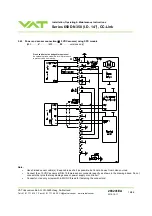
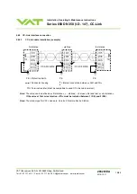
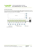
2.6.7 Digital
input
Pin
Function
Signal type Description
Priority
3
CLOSE VALVE
Digital
input
1)
This function will close the valve.
Valve will be in interlock mode as long as function is activated.
After deactivation of function it will remain effective until
- converse CC-Link control command have been received
The function is activated when optocoupler is ‘on’ in non
inverted configuration.
The function is activated when optocoupler is ‘off’ in inverted
configuration.
Configuration can be adjusted in local operation via service port
with CV, CPA or Hyper terminal. Refer to chapter: «LOGIC I/O
configuration».
1
2)
1
DIGITAL GROUND
Digital
ground
Ground for digital input. Connect switch to ground.
See also «2.6.6 LOGIC I/O» for details.
1) The digital input is digitally filtered. Filter delay is 50ms. This means that digital signal must be applied for at
least 50ms to be effective.
Refer to «2.6.6 LOGIC I/O» for details about input circuit.
2) Highest priority is 1. Functions with lower priorities will not be effective as long as higher priority functions
are active. The digital input has higher priority than all CC-Link and Local commands and higher priority than
freeze mode. CC-Link, Local commands and freeze mode will not be accepted while digital input is active.
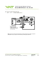
2.6.8 Digital
output
Pin
Function
Signal type Description
Priority
2
VALVE CLOSED
Digital
output
This function will indicate that the valve is closed.
4
DIGITAL COMMON
Digital
common
Common for all digital output. C or – terminal of source
with common.
See also «2.6.6 LOGIC I/O» for details.
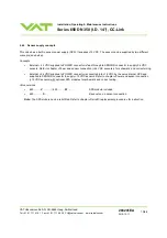
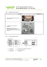
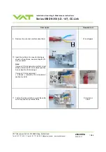
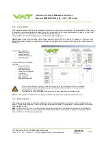
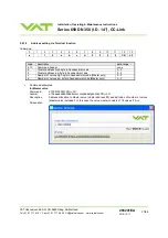
2.6.9 Service
port
connection
The service port (connector: SERVICE) allows to connect the valve to a RS232 port of a computer.
This requires a service cable and a software from VAT. You can either use our freeware 'Control View', which can be
downloaded from www.vatvalve.com or purchase our 'Control Performance Analyzer'.
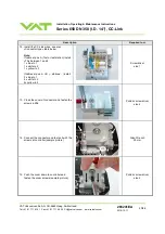
The service port is not galvanic isolated. Therefore we recommend using this only for setup, testing and maintenance and
not for permanent control.
Refer also to «Local Operation» for details and to «Spare parts / Accessories» for ordering numbers of service cable and
software.
Connector: Use only screws with 4-40UNC thread for fastening the service port connector!


