28
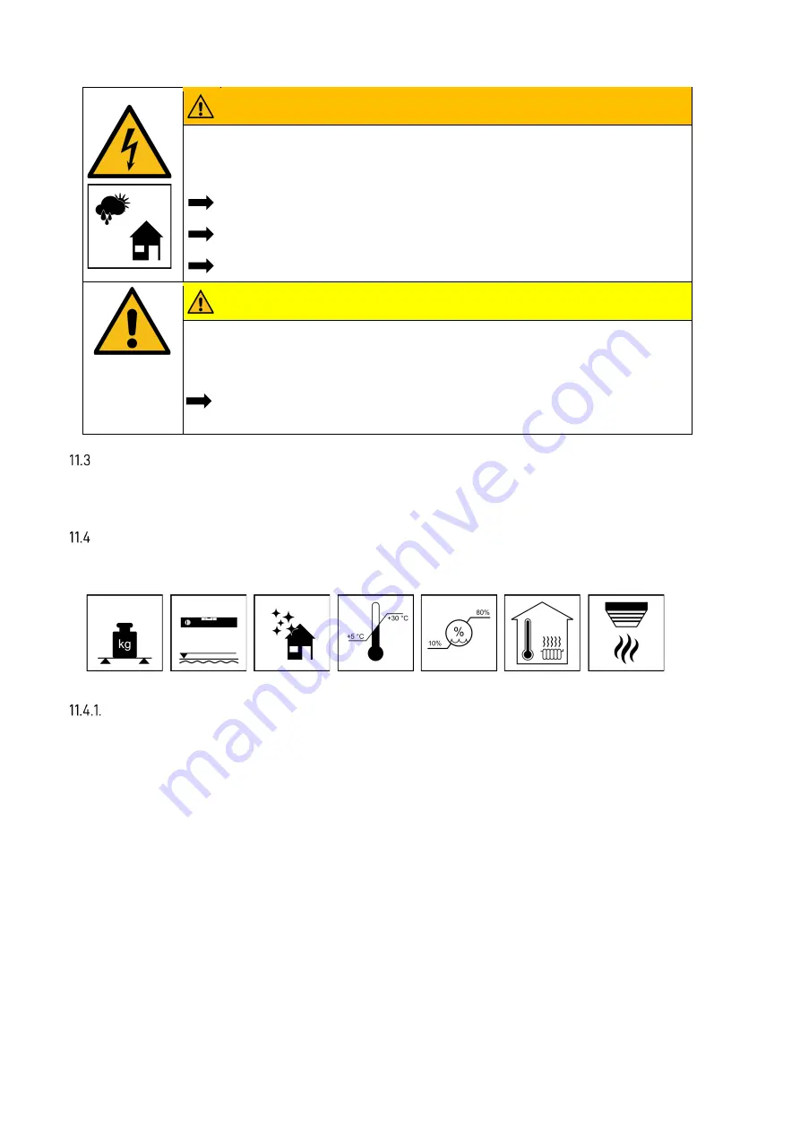
WARNING
Entry of water into electrical installations.
Danger to life due to electric shock.
Set up the storage cabinet only within buildings.
Pay attention to the IP protection class of the energy store
Comply with all the requirements concerning the setup site.
CAUTION
Personal and material damage due to erroneous setup and lack of space.
Crushing injuries to limbs.
Position the cabinet in such a way that hazard-free installation, operation,
maintenance and dismount is possible in the case of intended use.
Suitable assembly sites
Suitable sites include dry cellars, service entrance rooms and utility rooms.
At assembly, be aware that the operating noises of the energy store may be disruptive.
Assembly sites
Adhere to the following dimensions and conditions at the setup site:
Dimensions and equipment
Room volume min. 30 m
³
.
Wall surface of min. 200 cm x 90 cm (height x width).
The wall must be vertical and flat. The carrying capacity must be designed for 4 times the own
weight of the energy store. You will find the weight of the energy store in chapter 5.7 “Technical pa-
rameters”, page 17.
If appropriate, have the statics checked.
The subsurface, connecting walls and ceilings must not consist of heart-sensitive materials.
So that the cooling air can escape unhindered from the device, the distance to adjacent equipment
must not exceed 15 cm. A gap of at least 30 cm in height must be provided for above the housing.
A space of approx. 120 cm in depth in front of the device is required to be able to perform installation
and maintenance work on the front. The screws to open the housing must be accessible from below.
Pay attention to the minimum dimensions in Fig. 2 “Dimensions on the support plate” on page 35.
To ensure that escape is possible, the swivel range of doors must not extend into this space.
•
A smoke detector must be installed in the setup room of the VARTA pulse neo.
Содержание pulse neo
Страница 1: ...VARTA STORAGE GMBH OPERATING MANUAL VARTA pulse neo ...
Страница 16: ...16 System overview Identification Type plate and ID label Cryptocode label ID label of the battery module ...
Страница 35: ...35 All dimensions in millimetres Fig 2 Dimensions on the support plate ...
Страница 77: ...As at 07 2021 Appendix a Connection diagram TN C network ...
Страница 78: ...As at 07 2021 Appendix b Connection diagram TT network ...
Страница 79: ...As at 07 2021 Appendix c Connection diagram TN C network with data logger ...
Страница 80: ...As at 07 2021 Appendix d Connection diagram TT network with data logger ...


