959D Leak Detector
DRAFT
9/13/02
xiii
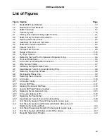
List of Figures
Figure Caption
Page
1-1
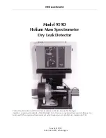
Model 959D Leak Detector ................................................................................................. 1-2
1-2
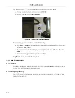
Rear Panel Circuit Breakers ............................................................................................... 1-6
1-3
959D Front View ................................................................................................................. 1-7
1-4
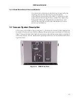
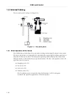
Vacuum System................................................................................................................ 1-10
2-1
Primary (left) and Secondary (right) Controls ..................................................................... 2-1
2-2
959D Primary Controls and Indicators ................................................................................ 2-2
2-3
Opening the Access Panel.................................................................................................. 2-3
2-4
Secondary Controls and Indicators..................................................................................... 2-4
2-5
959D Rear Panel Components ........................................................................................... 2-5
2-6
Vacuum Test Port ............................................................................................................... 2-6
2-7
Principal Test Controls........................................................................................................ 2-8
2-8
Range at Two Arcs ........................................................................................................... 2-15
2-9
N
2
Purge System .............................................................................................................. 2-16
3-1
Removing the Test Port Compression Ring and O-ring...................................................... 3-4
3-2
Front and Side Views.......................................................................................................... 3-5
3-3
Ion Source and Preamplifier Connectors ............................................................................ 3-6
3-4
Wing Nut and Clamp........................................................................................................... 3-7
3-5
Extracting the Spectrometer Tube ...................................................................................... 3-7
3-6
Spectrometer Tube O-ring and Centering Ring .................................................................. 3-8
3-7
Removing Flange Cap Screws ........................................................................................... 3-8
3-8
Disengaging Flange Cap .................................................................................................... 3-9
3-9
Removing the Ion Source ................................................................................................... 3-9
3-10
Ion Source......................................................................................................................... 3-10
3-11
Ion Source Cavity.............................................................................................................. 3-11
3-12
Ground Slit Plate............................................................................................................... 3-12
3-13
Cleaning the Ground Slit Plate.......................................................................................... 3-13
3-14
Ground Slit Plate Properly Inserted .................................................................................. 3-14
3-15
Replacing the Ion Source O-ring....................................................................................... 3-15
3-16
Ion Source Alignment Pin ................................................................................................. 3-16
3-17
Replacing the Preamplifier................................................................................................ 3-17
3-18
Spectrometer Tube O-ring and Centering Ring ................................................................ 3-18
A-1
Test Piece Evacuated: Tracer Probe Used to Locate Leak ................................................A-6
A-2
Test Piece Evacuated and Hooded with Helium Atmosphere to
Determine Overall Leak Rate..............................................................................................A-6
A-3
Test Piece Pressurized: Detector Probe Used to Locate Leak...........................................A-7
A-4
Test Piece Sealed with Helium and/or Other Gases...........................................................A-7
A-5
Magnetic Separation Principle ............................................................................................A-9
Содержание 959D
Страница 16: ...959D Leak Detector 1 2 D R A F T 9 1 3 0 2 Figure 1 1 Model 959D Leak Detector ...
Страница 28: ...959D Leak Detector This page intentionally left blank D R A F T 9 1 3 0 2 ...
Страница 48: ...959D Leak Detector This page intentionally left blank D R A F T 9 1 3 0 2 ...
Страница 68: ...959D Leak Detector This page intentionally left blank D R A F T 9 1 3 0 2 ...
Страница 78: ...959D Leak Detector This page intentionally left blank D R A F T 9 1 3 0 2 ...
Страница 81: ......

