


Agatha
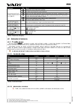
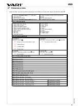
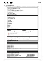
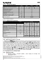
3.3.1.2 Engine information
Engine
Unit
Value
DS-521
DS-521B
DS-521Z
Type
-
HONDA GCV-160
Briggs & Stratton 675 Series™
VARI XP-200
Engine displacement
cm
3
160
190
196
Bore x stroke
mm
64 x 50
68,3 x 51,8
70 x 51
Max. power/at rpm (HP)
kW/min
-1
(HP)
3,3/3600 (4,4)
2,7/3200 (3,6)
3,6/3600 (4,8)
Max. torque/at rpm
N.m/min
-1
9,4/2500
9,2/3060
10/3000
Maximum (set) engine rpm
min
-1
3200
±
100
3200
±
100
3200
±
100
Fuel consumption
l (litre)
1,1 at
3000min
-1
1,55 at 3060min
-1
1,02 at 3600min
-1
Maximum engine tilt (long period)
20°
15°
15°
Maximum engine tilt (short period
30°
30°
30°
Fuel tank volume
l (litre)
0,91
1
1
Fuel
(unleaded) petrol
ON 91-95
ON 91-95
ON 91-95
Engine oil filling
l (litre)
0,55
0,6
0,6
Oil quality
SAE
SAE 10W-30
SAE 30
SAE 10W-30
SAE 30
SAE 10W-30
SAE 30
Ignition plug
-
NKG BPR6ES
CHAMPION RJ19LM
LG F6RTC
BRISK LR15YC
BRISK JR19
BRISK LR15YC
Tab. 5: Engine technical information
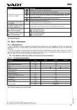
3.3.2 Description of the machine and its parts
Drum mower
Agatha
(
Pict.2
) is built on a steel frame, to which all important parts of the machine are attached. All
controls
1
,
2
and
4
are placed on the handlebars. Handlebars are attached to the frame with a
bolted
connection
3
and their height is adjustable
into 6 positions.
Handles
12
secure a firm grip and machine handling during work. On the left side of the handlebars, there is the
wheel
drive clutch
lever
2
which controls the movement of the machine in forward direction. On the right side, there is lever
1
of the disc
drive clutch for turning the cutting disk drive on (off). Both control levers return to their original position when the handlebars are released
in a critical situation and disconnect the engine power transfer. The cutting disk is equipped with an
automatic brake
disk. Engine speed is controlled with an
accelerator lever
4
. The wheel drive is controlled by worm-gear unit with a belt clutch which
provides fluent power transfer onto the wheels
15
(the machine does not start with a jump). The gearbox and clutch are covered by a
plastic
gearbox cover
16
. There is the
cutting disk
7
with four
steel blades
8
in the front part. The attendant is protected against
flying parts of the cut stand by
cover
10
and
9
. A detachable
side screen
6
, which is attached with a
bolted connection
5
,
controls the line spacing.
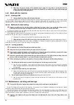
3.4 User guide
3.4.1 Assembling the machine
As part of the pre-sale servicing, ask your dealer to unwrap the machine and give you a brief training on
how to use it!
Places for holding the cutter while removing it from the box (see
Pict.1
): by the cutting disc in the front
4
, by the machine frame tube
in the back
1
.
3.4.1.1 Assembling procedure
Use the following procedure for assembling the machine:
(It is advised to assemble the machine with a second person’s assistance)
1)
According
Pict.1
3
, bag
6
, side and rear screens
7
and a screen holder
2
out of the box. Pick the
machine up by its lift points in front
4
and back
1
and take it out of the box.
2)
According
Pict.2
- dismount the bolted connection
3
on both sides of the frame, take off the handlebars, turn them around
and put them on the frame as shown in the picture (choose one of the 3 holes in the handlebars to set their height). Re-tighten
the bolted connection firmly with your hand.
Control lever cables must not be crossed - this shortens their lifetime
!
3)
Take the draw bands out of the bag and tighten brake cables to the handlebars where the upper bending of the handlebars
tube ends. Two pieces of draw bands are sufficient for cable tightening.
4)
Dismount the self-locking nuts
M5 (2 pieces) and washers, mounted by the manufacturer, off the frame and set the disc
cover on the machine so that the holes fit in the screws in the frame, and the narrowed part of the cover is pushed in under the
engine plate. Put the washers and self-locking nuts M5 back on the screws and tighten them.
76
Measured according to new
Society of Automotive Engineers (SAE) J1349 standard
77
Measured according to new
Society of Automotive Engineers (SAE) J1349 standard
78
Short period – up to 1 minute.
79
Measured according to new
Society of Automotive Engineers (SAE) J1349 standard
80
The automatic break is an active protective feature that supports the machine’s safety.
81
Using wrench (preferably tubular wrench) n.10.
32
R
ev
iz
e
0
4
/2
0
1
5
Содержание agatha DS-521
Страница 2: ......
Страница 25: ...Agatha 28 Revize 04 2015...
Страница 37: ...Agatha 40 Revize 04 2015...
Страница 39: ...Agatha 1 4 2 4 2 1 18 60 9 m s 1 EN 352 1 EN 352 2 20 10 EN 166 EN 1731 10 42 Revize 04 2015...
Страница 47: ...Agatha 2 10 11 2 10 1 2 1 115 116 4 5 5 10 2x 5 6 6 20 7 4 5 6 115 1 116 50 Revize 04 2015...
Страница 48: ...Agatha 8 4 5 7 6 MAX 4 5 7 1 4 5 8 117 4 5 9 Type C 117 51 Revize 04 2015...
Страница 50: ...Agatha 9 10 11 12 13 14 15 16 17 53 Revize 04 2015...
Страница 51: ...Agatha 54 Revize 04 2015...


