


Rev. 1.2
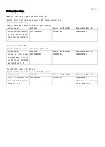
*Setting Procedures
With external trigger input connectors pins 1 to 4, select the channels (CH1 to CH2 to CH3 to CH4) where you want
to input an external trigger, and input trigger.
Trigger signals are input from the external trigger input connector in ON/OFF Mode and Strobe Mode in both Internal
Mode or External Mode.
ON/OFF Mode
The Light Units are turned ON or OFF according to the external trigger signal input.
Strobe Mode
The Light Units are turned ON for the set time after the external trigger signal input.
*Trigger Input Sequence Diagram
・A pulse width of ON signal shall be 10μs or more. The Light Units will be turned on for at least 40μs, even when the input ON
signal is less than 40μs.
・If another trigger is input before the Light Units turns OFF in Strobe Mode, the starting point of the reentered trigger is taken
as the start time and the strobe light continues for the set time from that point.
TRIG. IN
1
2
3
10
()
4