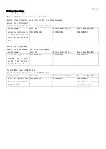
VAL VLC-1230-4 Скачать руководство пользователя страница 7

Rev. 1.2 


Setting Procedure 


-Make sure that the main power source is turned ON. 

-Set the Internal/External mode selector to EXT. to set External mode. 

-Setting the Light Intensity 

Specify the ID and the channel, and the light intensity. 

Setting example 

Send data 

Receive data(When ON) 

Receive data(When NG) 

Setting the light intensity 

to  75  for  CH2  of  the  VLC-

1230-4 that has the ID set 

to 01 

@01F07500E4CRLF 

@01O0051CRLF 

@01N0300B3CRLF 


-Setting the Lighting Mode 

Specify the ID and channel, and set the lighting mode. 

Setting example 

Send data 

Receive data(When ON) 

Receive data(When NG) 

Setting  the  lighting  mode 

to  Strobe  Mode  at  200μs 

for  CH2  of  the  VLC-1230-4 

that the ID set to 00. 

@00S0400B8CRLF 

@00O0050CRLF 

@00N0300B2CRLF 


-To set ON/OFF Signal in ON/OFF mode 

Specify the ID and the channel, and set ON/OFF signal. 

Setting example 

Send data 

Receive data(When ON) 

Receive data(When NG) 

To turn all light units OFF 

of the VLC-1230-4 that has 

the ID set to FF. 

@FFL000A8CRLF 

@FF007BCRLF 

@FFN0300DDCRLF 

(When there is a set value 

out of range error) 


Содержание VLC-1230-4

Страница 1: ... safety please read this manual thoroughly before starting operation Keep this manual for the whole product lifetime The following warning symbols are used in this manual Be sure to fully understand the contents WARNING A warning denotes a hazard that can cause severe injury or death CAUTION A caution denotes a hazard that can cause injury or damage of equipment ...

Страница 2: ...her lighting unit over current may cause a fire or heat CAUTION 1 USE the extension or remote cables 3m maximum to prevent power drop by voltage reduction or malfunction by noise 2 Installation of the product 1 Place horizontally in a well ventilated space on the rubber feet at the bottom of the unit 2 Do not topple or lay on its side 3 Do not put on unstable or vibrational place 4 Do not use in e...

Страница 3: ...ectors SMP 02V BC JST 1 output 2 output Insulation resistance 500MΩ min Withstand voltage AC1500V minute External control connectors Trigger input MIL connector MIL C 83503 compliant 10 pole For setting the light intensity and lighting mode e CON 3 pole Intensity Control INT Control manually by volume knobs EXT Remote control by external EIA 232 D Strobe Control NOR The lights are always ON STR St...

Страница 4: ...ings for Light Unit connected to output connector CH3 CH4 lit Lit when changing settings for Light Unit connected to output connector CH4 Control Switch Selects internal INT or external EXT control mode Mode Switch Selects normal NOR or strobe STR control mode Trigger H L Logic Switch Selects the logic of the trigger signal External Control Connector For external control with RS 232C communication...

Страница 5: ...S 232C or TRIG IN connector on front panel 4 On Off Control It is possible to turn off the light by inputting off signal by External control mode 5 Error Signal Error indicator on front panel will be on if an error of LED lighting unit detected such as breaking of wire Error signal from external signal connector will be output at the same time It does not identify error of CH1 or CH2 or CH3 or CH4...

Страница 6: ...s of the ASCII characters from the header to the ID are added the lowest byte is converted to hexadecimal and two characters are sent Example Setting the Light Intensity of Channel 2 to 125 Sent command ID Total Send Data 1 Instruction Data 2 Light Intensity Setting F 000 to 255 000 Min Intensity 255 Max Intensity 000 Lighting Mode Setting S 01 to 10 Refer to Lighting Mode Settings 00 ON OFF Setti...

Страница 7: ...01N0300B3CRLF Setting the Lighting Mode Specify the ID and channel and set the lighting mode Setting example Send data Receive data When ON Receive data When NG Setting the lighting mode to Strobe Mode at 200μs for CH2 of the VLC 1230 4 that the ID set to 00 00S0400B8CRLF 00O0050CRLF 00N0300B2CRLF To set ON OFF Signal in ON OFF mode Specify the ID and the channel and set ON OFF signal Setting exam...

Страница 8: ... turned ON Connector Layout External Trigger Input Connector Plug External Trigger Signal Connection Example Signal Specifications Rated input voltage Maximum input voltage ON voltage ON current OFF voltage OFF current ON OFF response time Input impedance 24 VDC 26 4 VDC 14 4 VDC min 3 mA max 5 VDC max 1 mA max 10 μs max 7 5kΩ per terminal TRIG IN 1 2 3 10 5 7 9 4 6 8 External Circuits VLP 2430 4 ...

Страница 9: ...r OFF according to the external trigger signal input Strobe Mode The Light Units are turned ON for the set time after the external trigger signal input Trigger Input Sequence Diagram A pulse width of ON signal shall be 10μs or more The Light Units will be turned on for at least 40μs even when the input ON signal is less than 40μs If another trigger is input before the Light Units turns OFF in Stro...

Страница 10: ...e performance specifications etc by customers after the day of product delivery Faults or damage that occur due to use of the product other than for its designed purpose Faults or damage that occur due to natural or human causes such as saltwater air damage gas damage earthquakes floods fire lighting or armed conflicts Disclaimer VS Technology Thailand Co Ltd shall not be responsible for any appen...

Отзывы: