*****INTERNAL*****30 R_D proof- 26.10.2022 / 09:15:46- VaillantGroup\DOC-agt\Brand\VIH_QW_190_6\ENG\OI-II_GB_0020291525
0020291525_04 Installation and maintenance instructions
25
5
6
3
4
4×1
2×1
30 mm
13 mm
6.
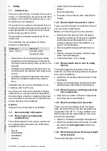
Disconnect the plug connection for the cylinder temper-
ature sensor
(6)
.
7.
Remove the four screws
(3)
.
8.
Unscrew the two nuts
(4)
on the pipe connections.
9.
Use the recessed handles
(5)
to lift off the upper part of
the product.
10.
To assemble the product, carry out the steps described
above in reverse order.
4.10
Removing the casing
4.10.1 Removing the front casing
2x1
2x1
1,5 x 5,5
1,5 x 5,5
D
E
C
A
A
B
1.
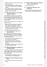
Remove the front flap on the control panel by taking
hold of the recessed handles with both hands and lift-
ing off the front flap towards you.
2.
Turn two screws on the right-hand side anti-clockwise
by a quarter turn each, and by a quarter turn clockwise
on the left-hand side. Pull the control panel cover for-
wards and out.
A
2×1
B
T20
3.
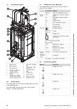
Remove both screws, raise the lower section of the
front casing and pull it forwards and out.
Note
All connecting screws in the housing parts
are Torx T20.
Содержание uniTOWER plus
Страница 2: ...2 en Operating instructions 3 en Installation and maintenance instructions 15...
Страница 71: ......


