Decommissioning the product 13
0020224355_00 HOME Installation and maintenance instructions
29
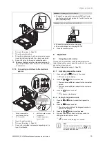
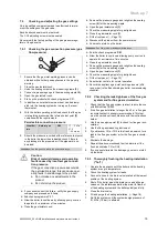
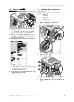
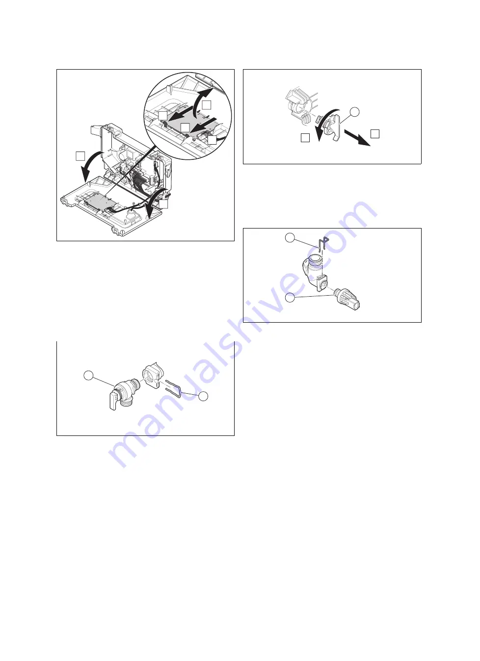
12.6.8 Replacing the PCB for the user interface
B
C
C
D
A
A
1.
Open the electronics box.
2.
Pull the plug out of the PCB.
3.
Undo the clips on the PCB.
4.
Remove the PCB.
5.
Install the new PCB in such a way that it clicks into the
groove at the bottom and into the clip at the top.
6.
Plug in the PCB plug.
7.
Close the electronics box.
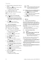
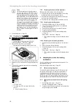
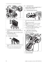
12.6.9 Replacing the expansion relief valve
1
2
1.
Remove the clip
(2)
.
2.
Remove the expansion relief valve.
3.
Fit the new expansion relief valve with a new O-ring.
4.
Reattach the clip
(2)
.
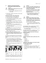
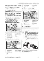
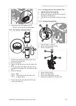
12.6.10 Replacing the flow sensor
1
B
A
1.
Pull out the plug.
2.
Remove the flow sensor
(1)
.
3.
Install the new flow sensor.
4.
Plug in the plug.
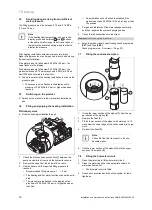
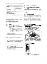
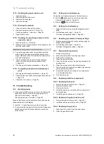
12.6.11 Replace the pressure sensor
1
2
1.
Pull out the plug.
2.
Remove the clip
(1)
.
3.
Remove the pressure sensor
(2)
.
4.
Install the new pressure sensor.
5.
Reattach the clip
(1)
.
12.7
Completing repair work
▶
Check that the product is running correctly and that it is
completely leak-tight.
13 Decommissioning the product
▶
Decommission the product.
▶
Disconnect the product from the power mains.
▶
Close the gas isolator cock.
▶
Close the cold water stop cock.
▶
Drain the product. (
→
Page 26)
14 Customer service
To ensure regular servicing, it is strongly recommended
that arrangements are made for a Maintenance Agreement.
Please contact Vaillant Service Solutions for further details.
Vaillant Service Solutions: 0330
100
3461
Содержание home combi
Страница 51: ......

