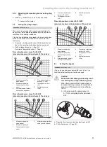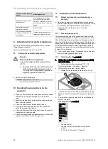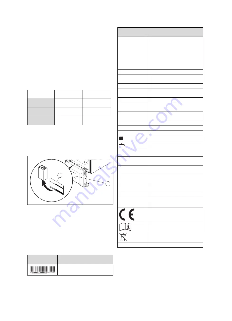
background image

Notes on the documentation 2

0020224355_00 HOME Installation and maintenance instructions

7

2

Notes on the documentation

2.1

Observing other applicable documents

You must observe all the operating and installation in-
structions included with the system components.

2.2

Storing documents

Pass these instructions and all other applicable docu-
ments on to the system operator.

2.3

Applicability of the instructions

These instructions apply only to:

Product article number

Article number

Gas Council Num-
ber

HOME COMBI 25
-A (H-GB)

0010019930

47-044-62

HOME COMBI 30
-A (H-GB)

0010019931

47-044-63

HOME COMBI 35
-A (H-GB)

0010019932

47-044-64

These products are only designed for natural gas systems.

3

Product description

3.1

Serial number


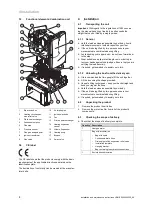
2

1

The serial number can be found on the identification plate

(1)

(

Page 7).

Stickers showing the serial number are on the back of the
electronics box

(2)

.

3.2

Information on the identification plate

The identification plate is mounted on the underside of the
product in the factory.

The identification plate keeps record of the country in which
the product is to be installed.

Information on the
identification plate

Meaning

Barcode with serial number

Information on the
identification plate

Meaning

Serial number

For quality control purposes; 3rd and 4th
digits = year of production
For quality control purposes; 5th and 6th
digits = week of production
For identification purposes; 7th to 16th
digits = product article number
For quality control purposes; 17th to 20th
digits = place of manufacture

HOME COMBI

Product description

XX, Gxx

xx mbar

(x kPa)

Gas group and gas connection pressure
as set at the factory

Cat.

Approved gas category

Condensing techno-
logy

Efficiency class of the boiler in accord-
ance with EC Directive 92/42/EEC

Type: Xx3(x)

Permissible flue gas connections

PMS

Maximum water pressure in heating
mode

PMW

Maximum water pressure in hot water
handling mode

V/Hz

Electric connection

W

Max. electrical power consumption

IP

Level of protection

Heating mode

Hot water generation

P

n

Nominal heat output range in heating
mode

P

nc

Nominal heat output range in heating
mode (condensing technology)

P

Nominal heat output range in hot water
handling mode

Q

n

Nominal heating load range in heating
mode

Q

nw

Nominal heating load range in hot water
handling mode

T

max.

Max. flow temperature

NOx

NOx class for the product

Code (DSN)

Specific product code

"CE label" section

Read the instructions.

"Recycling and disposal" section

GC no.

Gas council number

Содержание home combi

Страница 1: ...n and maintenance instructions HOME COMBI GB IE Installation and maintenance instructions Publisher manufacturer Vaillant GmbH Berghauser Str 40 D 42859 Remscheid Tel 49 21 91 18 0 Fax 49 21 91 18 28...

Страница 2: ...8 7 9 Checking and adjusting the gas settings 19 7 10 Checking function and leak tightness 20 8 Adapting the unit to the heating installation 20 8 1 Burner anti cycling time 20 8 2 Setting the pump ou...

Страница 3: ...Contents 0020224355_00 HOME Installation and maintenance instructions 3 J Combustion chart 46 K Lengths of the air flue pipe 47 L Technical data 47 Index 50...

Страница 4: ...ypes follow the specifications in these in structions Intended use includes the following observance of accompanying operating installation and servicing instructions for the product and any other sys...

Страница 5: ...fety devices in the system Observe the applicable national and inter national laws standards and guidelines 1 4 7 Risk of poisoning and burns caused by escaping hot flue gases Only operate the product...

Страница 6: ...HOME 0020224355_00 1 4 12 Risk of material damage caused by using an unsuitable tool Use the correct tool to tighten or loosen screw connections 1 5 Regulations directives laws standards Observe the...

Страница 7: ...plate Meaning Barcode with serial number Information on the identification plate Meaning Serial number For quality control purposes 3rd and 4th digits year of production For quality control purposes...

Страница 8: ...d reposition your feet If the unit is being lifted by two persons ensure your movements are coordinated during lifting Avoid bending your upper body do not lean forwards or to the side Wear suitable n...

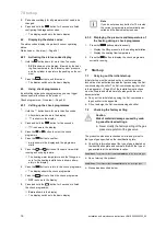
Страница 9: ...drill holes and make breakthroughs 4 8 Wall mounting the product 1 Check whether the wall has sufficient load bearing ca pacity to bear the operational weight of the product 2 Wall mount the product...

Страница 10: ...s remove only one side section never both side sections at the same time Note If there is sufficient lateral clearance at least 50 mm you can remove the side section to facilitate maintenance or repai...

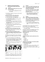
Страница 11: ...the system with thermal insulation Preliminary work 1 Check that the system volume and the volumetric capa city of the expansion vessel are the same If the volume of the expansion vessel is insuffici...

Страница 12: ...p small pockets of water close to the pipe wall which can freeze and build into a larger ice plug As with other pipe work insulate the condensate dis charge pipe to minimise any risk of freezing and b...

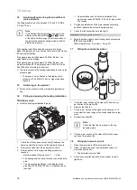
Страница 13: ...n attachment for separate lines must lead to a 50 cm sided square For each additional 90 elbow or two 45 elbows that is required the length L must be reduced by 1 m Length of the C13 type flue pipe Pa...

Страница 14: ...rrying out the wiring 30 mm max 1 Shorten the connection cables to the appropriate lengths to prevent them from causing damage inside the electronics box 2 Screw the plug to the connection cable 3 Plu...

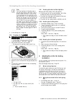
Страница 15: ...inuous pump operating mode Conditions If you are connecting a controller 230 V 30 mm N L X1 230V RT Connect the controller to the main plug Remove the bridge from the plug 24V RT 4 Close the electroni...

Страница 16: ...ck programme OFF is shown in the display 8 Press and hold the button for 3 seconds to finish the check programmes End is shown in the display The display switches to the basic display Note If you do n...

Страница 17: ...f the heating water is less than 6 5 or more than 8 5 Total heating output Water hardness at specific system volume 1 20 l kW 20 l kW 50 l kW 50 l kW kW ppm CaCO mol m ppm CaCO mol m ppm CaCO mol m 50...

Страница 18: ...r vent and the hydraulic console 2 Remove the caps from the automatic air vents 3 Fill with water until the required filling pressure is reached Recommended filling pressure 1 1 5 bar The heating and...

Страница 19: ...w 2 for the measuring nipple Open the gas isolator cock 1 Check the measuring nipple for gas tightness Close the gas isolator cock 1 Fit the front panel Page 10 Disconnect the product from the power m...

Страница 20: ...k the gas line the flue gas installation the heating installation and the hot water pipes for leaks Check that the air flue pipe and condensate drain pipe work have been installed correctly Check that...

Страница 21: ...put in circuit l h B Available pressure kPa Flow rate pressure curves for 30 kW pressure measured downstream of the valves 2 1 3 4 60 70 50 30 20 40 10 0 500 1000 1500 A B 1 Maximum speed by pass clos...

Страница 22: ...uct maintained on a regular basis Instruct the operator about measures taken to ensure the supply of combustion air and flue gas pipe 11 Inspection and maintenance 11 1 Observing inspection and mainte...

Страница 23: ...d front cas ing installed front casing Natural gas G20 CO at full load 9 2 0 2 Set for Wobbe index W 14 09 kW h m O at full load 4 5 1 8 vol CO at full load 250 ppm CO CO 0 0027 If the setting is not...

Страница 24: ...to the condensate tray 11 7 Checking the burner 1 Search the surface of the burner for possible damage If you see any damage replace the burner 2 Install the two new burner seals 11 8 Checking the ign...

Страница 25: ...Reinsert the float 3 Note Check whether the float is present in the condensate siphon 6 Clip the lower section of the siphon 1 into the upper section of the siphon 2 11 11 Cleaning the filter in the c...

Страница 26: ...wn for more than 3 seconds If you are unable to clear the fault code and it reappears despite several fault clearance attempts contact cus tomer service 12 2 Calling up the fault memory The last ten f...

Страница 27: ...ll in place on the fan 7 9 Install the new gas valve in reverse order 10 Check the CO content Page 22 11 Set the CO content Page 23 12 6 4 Replacing the heat exchanger 1 Remove the gas air mixture uni...

Страница 28: ...e pump cable to the electronics box 12 6 6 Replacing the expansion vessel 1 Drain the product Page 26 B C 1 2 3 A D 2 Undo the nut 3 3 Remove both screws on the support plate 1 4 Remove the support pl...

Страница 29: ...ng the flow sensor 1 B A 1 Pull out the plug 2 Remove the flow sensor 1 3 Install the new flow sensor 4 Plug in the plug 12 6 11 Replace the pressure sensor 1 2 1 Pull out the plug 2 Remove the clip 1...

Страница 30: ...unction is active for 15 minutes P 06 Purging the heating circuit The diverter valve is moved to the heating position The function is activated in the heating circuit for 15 minutes The pump runs and...

Страница 31: ...ng circuit s shunt pump Current value off on Not adjustable d 13 Status of the hot water circuit s circulation pump Current value off on Not adjustable d 14 Operating mode of the modulating pump 0 5 0...

Страница 32: ...inder charging pump 4 Extractor hood 5 External solenoid valve 6 External fault message 7 Solar pump omitted 8 eBUS remote control 9 Legionella protection pump 10 Solar valve 1 Adjustable d 28 Functio...

Страница 33: ...Function deactivated on Function activated 1 Adjustable d 67 Remaining burner anti cycling time setting un der d 02 Current value min Not adjustable d 68 Number of unsuccessful ignitions at 1st attem...

Страница 34: ...CB Adjustable d 96 Default setting reset 0 No 1 Yes Adjustable d 128 Heating minimum target value 10 75 1 10 Adjustable d 129 Minimum hot water tar get value 35 com bination unit 45 pure boiler 60 1 3...

Страница 35: ...heating and hot water request blocked S 97 Automatic test programme Water pressure sensor heating and hot water request blocked S 98 Automatic test programme Return temperature sensor heating and hot...

Страница 36: ...in pressure monitor defective line removed from between the pressure monitor and silencer air flue pipe blocked and silencer not installed properly F 49 eBUS fault Voltage too low Short circuit on eB...

Страница 37: ...turn temperature sensors have been inverted flow and return temperature sensors have not been correctly installed F 85 Fault Temperature sensor The flow and or return temperature sensors have been ins...

Страница 38: ...FUS X106 X32 X90 X12 X35 X1 X21 L N RT 230Vac L N X35 1 3 4 1 3 3 1 2 M 1 3 4 6 1 2 3 eBUS Burner off X106 M 5 4 2 1 2 1 2 1 N L L 24V 230V 24V 230V 2 8 9 10 11 13 12 1 5 4 3 6 7 15 14 1 Main PCB 2 In...

Страница 39: ...9 3 15 4 5 10 11 6 13 X51 X1 X21 L N L N 1 3 4 1 3 3 1 2 M 1 3 4 6 1 2 3 eBUS Burner off X106 M 4 3 2 1 5 4 2 1 5 6 7 8 2 1 2 1 N L X35 X35 24V 230V 24V 230V 2 8 9 10 11 13 12 1 5 4 6 7 15 14 3 1 Main...

Страница 40: ...g pres sure X 9 Check the ignition electrode X X 10 Remove the gas air mixture unit X 11 Replace both burner seals each time it is opened and accordingly each time maintenance work is carried out X 12...

Страница 41: ...s 75 mm E Below eaves 200 mm F Below balconies or car port roofs 200 mm G From vertical wastewater pipes or down pipes 150 mm H From external or internal corners 200 mm I Above floors roofs or balconi...

Страница 42: ...ithout affecting the performance of the boiler In order to ensure that the condensate vapour plume does not damage adjacent surfaces the terminal should be exten ded as shown Dimension H This clearanc...

Страница 43: ...ance instructions 43 I Commissioning Checklist Heating and Hotwater Industry Council HHIC www centralheating co uk Benchmark Commissioning and Servicing Section It is a requirement that the boiler is...

Страница 44: ...he appropriate Building Regulations and then handed to the customer to keep for future reference GAS BOILER SYSTEM COMMISSIONING CHECKLIST CONTROLS Optimum start control Fitted Fitted Fitted Fitted AL...

Страница 45: ...stem is serviced regularly and that the appropriate Service Interval Record is completed Service Provider SERVICE RECORD SERVICE 01 AND AND SERVICE 02 AND AND SERVICE 03 AND AND SERVICE 04 AND AND SER...

Страница 46: ...cify how to set boiler to minimum rate contact Technical Helpline for advice CHECK CO AND COMBUSTION RATIO AT MINIMUM RATE With boiler still set at minimum rate insert analyser probe into flue gas sam...

Страница 47: ...A H GB HOME COMBI 30 A H GB HOME COMBI 35 A H GB Maximum heating flow temperat ure default setting 75 75 75 Max range of the flow temperat ure regulation 10 80 10 80 10 80 Maximum permissible pressure...

Страница 48: ...e range 35 60 35 60 35 60 Throughflow volume limiter 10 l min 12 l min 14 l min Technical data General HOME COMBI 25 A H GB HOME COMBI 30 A H GB HOME COMBI 35 A H GB Diameter of the gas pipe 1 2 inch...

Страница 49: ...filled with water 36 kg 37 1 kg 37 2 kg Technical data Electrics HOME COMBI 25 A H GB HOME COMBI 30 A H GB HOME COMBI 35 A H GB Electric connection 230 V 50 Hz 230 V 50 Hz 230 V 50 Hz Built in fuse sl...

Страница 50: ...onnection piece 12 Front casing closed 5 Frost 5 H Handing over to the operator 22 I Identification plate 7 If you smell gas 4 Inspection work 22 40 Installation site 5 Intended use 4 M Mains connecti...

Страница 51: ......
Страница 52: ...ables 0207 022 0928 Vaillant Service Solutions 0330 100 3461 Spares Technical Enquiries 01773 596615 info vaillant co uk technicalspares groupservice co uk www vaillant co uk These instructions or par...

Отзывы: