Installation Manual auroMATIC 560 0020060907_00
4
4.4
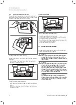
Fitting the controller housing
The controller is designed for fastening to a wall and is
fitted with System ProE connector strips, to which all the
customer-side connections must be made.
Fig. 4.2 Opening the controller housing
The housing cover is in two parts which can be removed
separately.
• Pull the lower front cover away from the controller
housing, as shown in Fig. 4.2.
C1/C2
C1
C2
KOL1
2 1
SP1
2 1
SP2
2 1
SP3
2 1
Ertrag
2 1
KOL2
2 1
230 V~
PE N L
KOL1-P
PE N L
LEG/BYP
PE N L
LP/UV1
PE N L
EP
2 1
KOL2-P/ZP
PE N L
1
2
Fig. 4.3 Fixing the controller housing
• Draw inside the two fixing holes (
1
and
2
) and drill the
holes.
• Select the wall plugs to suit the type of wall and screw
the housing tight.
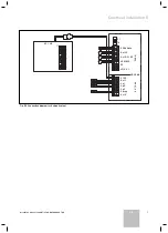
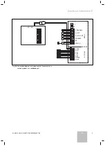
System-ProE wiring
C1/C2
C1
C2
KOL1
2 1
SP1
2 1
SP2
2 1
SP3
2 1
Ertrag
2 1
KOL2
2 1
230 V~
PE N L
KOL1-P
PE N L
LEG/BYP
PE N L
LP/UV1
PE N L
EP
2 1
KOL2-P/ZP
PE N L
3
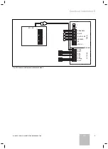
Fig. 4.4 Folding up the operating section
• Fold the operating section upwards.
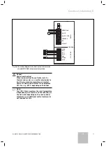
• Wire the controller unit in accordance with the select-
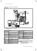
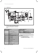
ed hydraulic plan (see Section 5.1).
• Fix all cables with the accompanying cable clamps (
3
).
• Fold the operating section down.
• Push the front cover on again.
5 Electrical
installation
The electrical connection may only be carried out by a
suitably qualified heating engineer.
e
Danger!
Risk of fatal electric shock from touching live
connections. Before working on the unit, turn
off the power supply and secure against switch-
ing on again.
a
Caution!
Risk of damage to the PCB as a result of short
circuits to the connecting cables. For safety
reasons, the ends of cables carrying 230 V
must not have more than 30 mm of the sheath
stripped back for connecting to a ProE connec-
tor. If a greater length is stripped back, there is
a risk of short circuits to the PCB.
Caution!
Pay attention to the sensor characteristics
when exchanging the controller units in existing
installations (see Section 11). Replace the sen-
sors if necessary!
4 Installation
5 Electrical installation
Содержание auroMATIC 560
Страница 1: ...auroMATIC 560 VRS 560 ES GB ...
Страница 2: ......
Страница 4: ......
Страница 16: ......
Страница 44: ......
Страница 46: ......
Страница 84: ...0020060907_00 ESGB 122007 ...


