background image

Operating Manual auroMATIC 560 0020060907_00

10

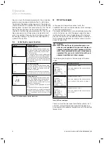
5.4.5 Service/diagnostics 

level 

display

Testing of the actuators and sensors should be carried 
out by an expert technician.
You can access the service/diagnostics level by pressing 
the programming button P and the dial simultaneously 
for at least three seconds. All the actuators and sensors 
can be activated and tested in this level (see Installation 
manual, Chapter 7).
The display reverts to the main operating level when you 
press the programming button. 

5.4.6  Installer level display

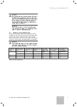
The parameters in the installer level should only be set 
by an expert technician.
You can access the installer level by pressing program-
ming button P for at least three seconds. 
To return to the basic display, press the programming 
button briefly.

5.5 Settings

5.5.1 

Calling up settings and operating values

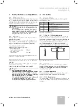
You can call up the set values consecutively by pressing 
the info button several times.
The information called up in each case is visible in the 
display for approximately five seconds, after which the 
display reverts to the main operating level.

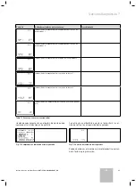
Display

Settings

Cylinder temperature target value
Yield

Temperature of cylinder sensor 1

Temperature of cylinder sensor 2

Temperature of cylinder sensor 3 (if con-
nected)

Table 5.1  Settings and operating values

Display

Settings

Temperature of collector sensor 1

Temperature of collector sensor 2 (if con-
nected)

Operating hours for solar pump 1

Operating hours for solar pump 2

Timer programme for heating window

Table 5.1  Settings and operating values (cont.)

Further timer programmes will be displayed here, de-
pending on how many you have set (see Sections 5.5.3 
and 5.5.4).

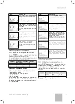
5.5.2  Settings in the main operating level

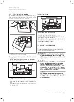
In the main operating level you can set:
–  

Cylinder temperature target value

–  

Operating mode

–  

Current day of the week

–  

Current time of day

The setting called up in each case can be viewed and set 
in the display for approximately five seconds, after 
which the display reverts to the basic display of the 
main operating level. Click the dial before the five sec-
onds have expired to access the next setting.

5 Operation

Содержание auroMATIC 560

Страница 1: ...auroMATIC 560 VRS 560 ES GB ...

Страница 2: ......

Страница 3: ...Para el usuario para el instalador especializado Instrucciones de uso y de instalación auroMATIC 560 Regulador diferencial solar VRS 560 ES ...

Страница 4: ......

Страница 5: ... Funciones especiales 7 4 9 1 Función fiesta 7 4 9 2 Recarga puntual 7 4 9 3 Función vacaciones 7 4 10 Prioridad del acumulador 7 4 11 Función de protección contra heladas 7 4 12 Función de protección del circuito solar 8 4 13 Funcionamiento adicional de la bomba solar función del colector tubular 8 5 Uso 8 5 1 Guía del usuario 8 5 2 Vista general de los elementos de mando 8 5 3 Vista general de l...

Страница 6: ... Documentación de validez paralela Al utilizar el regulador diferencial solar auroMATIC 560 observe todas las instrucciones de uso de las piezas y componentes de la instalación Dichas instrucciones de uso acompañan a todas las piezas de la instalación así como a los componentes complementarios 1 1 Conservación de la documentación Conserve estas instrucciones de uso y de instalación así como el res...

Страница 7: ...conocimiento de la misma La garantía excluye expresamente averías producidas por a Uso inadecuado del bien o no seguimiento del proce dimiento de instalación y mantenimiento descrito en el libro de instrucciones y demás documentación faci litada a tal efecto b Sobrecarga de cualquier índole c Manipulación de los equipos por personas no autori zadas 3 2 Uso adecuado El regulador solar auroMATIC 560...

Страница 8: ... la recarga del acumulador a través del genera dor de calor externo o el calentador eléctrico de inmer sión El retraso de recarga se activa en el nivel del especialis ta 4 4 Protección contra las legionelas La función de protección contra la legionela sirve para destruir los gérmenes existentes en las tuberías y en el acumulador Con la función activada se calientan a una hora fijada una vez por se...

Страница 9: ...car inequívocamente el acumulador a través de los sensores del acumulador acumulador 1 SP 2 acumulador 2 SP 3 Este ajuste solo se puede modificar en el nivel del espe cialista El acumulador con la máxima prioridad se carga siempre cuando la temperatura del colector es superior a la suma de la temperatura real en el acumulador más la di ferencia de conexión ajustada El acumulador ya no se carga cua...

Страница 10: ...a temperatura del acumulador es de al menos 10 C la bomba solar trabaja hasta calentar el acumulador ter mostato diferencial Si hay dos circuitos solares conectados la activación de la función del colector tubular afecta a ambos La fun ción se lleva a cabo de forma separada para cada campo de colector 5 Uso 5 1 Guía del usuario El regulador cuenta con una pantalla compuesta por símbolos y se basa ...

Страница 11: ...ra nominal 6 Modo de servicio actual 5 4 2 Pantalla del nivel de información Accede al nivel de información pulsando la tecla de in formación Primero aparece la indicación que figura abajo Puede consultar otras informaciones pulsando re petidamente la tecla de información véase aparta do 5 5 1 Las informaciones consultadas aparecen en pantalla durante unos 5 segundos después la indicación vuelve a...

Страница 12: ...ulo 7 La indicación volverá al nivel principal de manejo cuando pulse la tecla de programación 5 4 6 Pantalla del nivel del especialista En el nivel del especialista los parámetros solo los debe ajustar un instalador especializado Se accede al nivel del especialista pulsando la tecla de programación P durante al menos tres segundos Para retroceder de nuevo a la indicación básica pulse brevemente l...

Страница 13: ...íodos de tiempo El regulador está equipado con un programa básico que puede adaptar a sus necesidades individuales Período de tiempo Día de la semana bloque de semana Hora de inicio Hora de para da H 1 LU DO 5 30 22 00 H 2 H 3 Tabla 5 3 Programa básico de recarga El ajuste de los horarios deseados se lleva a cabo en cuatro pasos 1 Seleccione el período de tiempo 2 Seleccionar día o bloque de la se...

Страница 14: ...lación funcionará innecesariamente y enfriará poco a poco el acumulador 5 6 Activar las funciones especiales Pantalla Pasos necesarios Función fiesta Pulse una vez la tecla de función espe cial en la pantalla parpadea diez segun dos aprox el símbolo de fiesta y a conti nuación la función está activada La función se desactiva automáticamente al llegar al siguiente periodo de recarga Si desea desact...

Страница 15: ...servicio de asistencia técni ca oficial Le recomendamos firmar un contrato de mantenimiento de su instalación solar con su servicio de asistencia técnica oficial La siguiente tabla aclara el significado de los avisos Pantalla Aviso significado del aviso Error sensor de acumulador 1 Este error aparece cuando el sensor co nectado está averiado Error sensor de acumulador 2 Este error aparece cuando e...

Страница 16: ......

Страница 17: ...iones 3 4 Montaje 3 4 1 Material suministrado 3 4 2 Montaje de la sonda estándar VR 10 3 4 3 Accesorios 3 4 3 1 Sonda estándar VR 10 3 4 3 2 Sensor del colector VR 11 4 4 4 Montar la carcasa del regulador 4 5 Instalación eléctrica 4 5 1 Cableado según el esquema hidráulico 5 5 2 Esquema hidráulico 1 6 5 3 Esquema hidráulico 2 12 5 4 Esquema hidráulico 3 16 6 Puesta en servicio 20 6 1 Ajustar parám...

Страница 18: ... para el producto y el medio ambiente h Observación Informaciones e indicaciones útiles Símbolo que indica una actividad que debe realizarse 1 3 Validez de las instrucciones Estas instrucciones de instalación sólo tienen validez para los aparatos con las siguientes referencias de artí culo 306764 306767 El número de artículo de su aparato se encuentra en la placa de características 2 Descripción d...

Страница 19: ... no deberán utilizarse como bornes de apoyo para más cableado La instalación de la centralita de regulación deberá efec tuarse en locales secos h Peligro Peligro de escaldadura a causa del agua calien te La temperatura del acumulador de agua caliente solar puede exceder claramente los 60 C no solo mediante el calentamiento solar sino tam bién cuando se activa la función de protección contra las le...

Страница 20: ... 1 KOL2 2 1 230 V PE N L KOL1 P PE N L LEG BYP PE N L LP UV1 PE N L EP 2 1 KOL2 P ZP PE N L 3 Fig 4 4 Abrir el elemento de mando Ahora debe abatir el elemento de mando hacia arriba Efectúe el cableado del regulador según el esquema hidráulico seleccionado véase párrafo 5 1 Asegure todas las líneas con las descargas de tracción suministradas 3 Ahora debe abatir el elemento de mando hacia abajo Vuel...

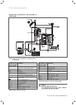
Страница 21: ...tar la instalación se han colocado tres esque mas hidráulicos en el regulador de los que deberá esco gerse el adecuado en función de la configuración de la instalación Los esquemas hidráulicos presentan una posible configu ración respectivamente si bien algunos de los compo nentes de la misma son opcionales a Atención Estos planos hidráulicos son sólo representacio nes esquemáticas y no pueden uti...

Страница 22: ...K Circuito s de calentamiento kW Agua fría ZP Bomba de circulación EP Calentador eléctrico de inmersión opcional Col1 P Bomba del circuito solar 1 Col 1 Sensor de colector 1 Ertrag Ganancia LegP Bomba de protección contra las legionelas Sp1 Sensor de acumulador 1 Sp2 Sensor del acumulador 2 S Contactor Tabla 5 2 Leyenda de la fig 5 1 y fig 5 2 Denominación en esquema hidráu lico esquema de conexio...

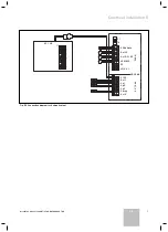
Страница 23: ...n auroMATIC 560 0020060907_00 ES 230V Netz F 1 T4 Kol 1 P Kol 2 P ZP LEG BYP EP LP UV 1 VRS 560 C1 C2 Kol 1 Sp 1 Sp 2 Sp 3 Ertrag Kol 2 5 V 24 V 230 V VC VK Fig 5 2 Esquema de conexiones de plan hidráulico 1 Instalación eléctrica 5 ...

Страница 24: ...V 1 en estado sin corriente A Conexión alternativa del segundo acumulador Col1 P Bomba del circuito solar 1 Col 1 Sensor de colector 1 Ertrag Ganancia LegP Bomba de protección contra las legionelas Sp1 Sensor de acumulador 1 Tabla 5 3 Leyenda de la fig 5 3 y fig 5 4 Denominación en esquema hidráu lico esquema de conexiones Componente Sp2 Sensor del acumulador 2 Sp3 Sensor del acumulador 3 S Contac...

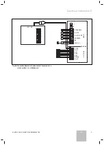
Страница 25: ...0907_00 ES 230V Netz F 1 T4 Kol 1 P Kol 2 P ZP LEG BYP EP LP UV 1 VRS 560 C1 C2 Kol 1 Sp 1 Sp 2 Sp 3 Ertrag Kol 2 5 V 24 V 230 V VC VK Fig 5 4 Esquema de conexiones de plan hidráulico 1 Conexión de un segundo acumulador o piscina Instalación eléctrica 5 ...

Страница 26: ...lentes Denominación en esquema hidráulico esquema de co nexiones Componente VED Calentador de agua instantáneo eléctrico Vaillant kW Bomba de circulación Col1 P Bomba del circuito solar 1 Col 1 Sensor de colector 1 Sp1 Sensor de acumulador 1 Sp2 Sensor del acumulador 2 230V Conexión 230V red F 1 T4 Pinza portafusible Red de 230V Entrada de red Ertrag Sensor de ganancia opcional Tabla 5 4 Leyenda d...

Страница 27: ...ecalentamiento Al integrar el regulador instale por principio un válvula mezcladora térmica para limitar la tem peratura máxima como medida de protección del regulador y ante escaldaduras Ajústelo en función del calefactor por ejemplo a 60 C h Observación El VED E Solar controla de forma autónoma la temperatura de entrada y se conecta en función de la temperatura del acumulador solar el reca lenta...

Страница 28: ... calentamiento kW Agua fría EP Calentador eléctrico de inmersión opcional Col1 P Bomba del circuito solar 1 Kol2 P Bomba del circuito solar 2 Col 1 Sensor de colector 1 Col 2 Sensor de colector 2 Ertrag Ganancia LegP Bomba de protección contra las legionelas Sp1 Sensor de acumulador 1 Sp2 Sensor del acumulador 2 S Contactor Tabla 5 5 Leyenda de la fig 5 7 y fig 5 8 Denominación en esquema hidráu l...

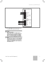
Страница 29: ...n auroMATIC 560 0020060907_00 ES 230V Netz F 1 T4 Kol 1 P Kol 2 P ZP LEG BYP EP LP UV 1 VRS 560 C1 C2 Kol 1 Sp 1 Sp 2 Sp 3 Ertrag Kol 2 5 V 24 V 230 V VC VK Fig 5 8 Esquema de conexiones de plan hidráulico 2 Instalación eléctrica 5 ...

Страница 30: ...exión alternativa del segundo acumulador Col1 P Bomba del circuito solar 1 Kol2 P Bomba del circuito solar 2 Col 1 Sensor de colector 1 Col 2 Sensor de colector 2 Ertrag Ganancia LegP Bomba de protección contra las legionelas Sp1 Sensor de acumulador 1 Tabla 5 6 Leyenda de la fig 5 9 y fig 5 10 Denominación en esquema hidráu lico esquema de conexiones Componente Sp2 Sensor del acumulador 2 Sp3 Sen...

Страница 31: ...0907_00 ES 230V Netz F 1 T4 Kol 1 P Kol 2 P ZP LEG BYP EP LP UV 1 VRS 560 C1 C2 Kol 1 Sp 1 Sp 2 Sp 3 Ertrag Kol 2 5 V 24 V 230 V VC VK Fig 5 10 Esquema de conexiones de plan hidráulico 2 Conexión de un segundo acumulador o piscina Instalación eléctrica 5 ...

Страница 32: ... K Circuito s de calentamiento kW Agua fría EP Calentador eléctrico de inmersión opcional Col1 P Bomba del circuito solar 1 Col 1 Sensor de colector 1 Kol2 P Bomba de recarga 2 Col 2 Sensor de recarga 2 Ertrag Ganancia LegP Bomba de protección contra las legionelas Sp1 Sensor de acumulador 1 Sp2 Sensor del acumulador 2 S Contactor 1 Activación del contactor para un calentador eléctrico de inmersió...

Страница 33: ...n auroMATIC 560 0020060907_00 ES 230V Netz F 1 T4 Kol 1 P Kol 2 P ZP LEG BYP EP LP UV 1 VRS 560 C1 C2 Kol 1 Sp 1 Sp 2 Sp 3 Ertrag Kol 2 5 V 24 V 230 V VC VK Fig 5 12 Esquema de conexiones de plan hidráulico 3 Instalación eléctrica 5 ...

Страница 34: ...el usuario LP UV 1 Válvula de conmutación UV 1 en estado sin corriente A Alternativo Col1 P Bomba del circuito solar 1 Col 1 Sensor de colector 1 Kol2 P Bomba de recarga 2 Col 1 Sensor de colector 1 Col 2 Sensor de recarga 2 Ertrag Ganancia LegP Bomba de protección contra las legionelas Sp1 Sensor de acumulador 1 Tabla 5 8 Leyenda de la fig 5 13 y fig 5 14 Denominación en esquema hidráu lico esque...

Страница 35: ...0907_00 ES 230V Netz F 1 T4 Kol 1 P Kol 2 P ZP LEG BYP EP LP UV 1 VRS 560 C1 C2 Kol 1 Sp 1 Sp 2 Sp 3 Ertrag Kol 2 5 V 24 V 230 V VC VK Fig 5 14 Esquema de conexiones de plan hidráulico 3 Conexión de un segundo acumulador o piscina Instalación eléctrica 5 ...

Страница 36: ...5l min 0 Restablecimiento de la ganancia solar Girando el botón de ajuste hasta el 1 se fija la ganancia solar en 0 Restablecimiento de las horas de servicio Girando el botón de ajuste hasta el 1 se fijan las horas de servicio en 0 Ajuste de la temperatura máxima del acumu lador 1 20 a 90 C 75 C Tabla 6 1 Parámetros de la instalación a Atención La temperatura máxima permitida del acumula dor utili...

Страница 37: ...C 60 C Tabla 6 1 Parámetros de instalación continuación a Atención La temperatura máxima permitida del acumula dor utilizado MAXT 2 no debe excederse Pantalla Ajuste girando el botón de ajuste Margen de ajuste Ajuste de fábrica Ajuste de la diferencia de conexión del acu mulador 2 La diferencia de conexión debería ser siem pre 2K superior que la diferencia de desco nexión 2 25K 7K Ajuste de la dif...

Страница 38: ...2 1 LEG Función de protección contra las legionelas OFF 1 2 3 4 5 6 7 1 7 OFF LEGT Tiempo de inicio de la función de protección contra las legionelas 00 00 23 50 04 00 Activar el retraso de recarga 0 desactivada 1 activada 0 Activación del control de duración de co nexión 0 desconectada 1 conectada 0 Ajustar el día actual 1 31 0 Ajustar el mes actual 1 12 0 Ajustar el año actual 2000 2015 2000 Tab...

Страница 39: ... a los ajustes de fábrica Puede devolver los parámetros de la instalación y los programas de tiempo a sus valores ajustados en fábrica pulsando durante 10 segundos la tecla de programa ción P La indicación parpadea tres veces y se devuelven todos los parámetros al ajuste de fábrica Puesta en servicio 6 ...

Страница 40: ...o prueba de la bomba de recirculación con esquema hidráulico 1 Bomba del colector 2 en marcha resto de activa dores desactivados Prueba de la válvula de conmutación Válvula de conmutación en marcha todos los demás actores desactivados Prueba de la bomba de protección contra las legionelas Bomba contra legionela en marcha resto de acto res desactivados Prueba de la resistencia eléctrica de inmersió...

Страница 41: ...lector 1 Indicación de temperatura del sensor de colector 2 Indicación de la temperatura del retorno sensor de ganan cia Tabla 7 1 Actores y sensores continuación Haciendo nuevamente clic en el botón de ajuste puede comprobar las indicaciones de pantalla Fig 7 1 Comprobar las indicaciones de la pantalla Con otro clic en el botón de ajuste se le mostrará la ver sión de software a disposición del re...

Страница 42: ...e potencia de centralita de regulación Carga de contacto de los relés iniciales máx Electricidad total máxima V CA Hz W A A 230 50 máx 10 2 4 La distancia de conexión más corta Reserva de funcionamiento Temperatura ambiente máx permitida Tensión de funcionamiento del sensor min min C V 10 30 50 5 Sección transversal mínima de las líneas de sonda mm2 0 75 de las líneas de conexión 230V mm2 1 5 Dime...

Страница 43: ...5710 ohm 20 C 12490 ohm 25 C 10000 ohm 30 C 8057 ohm 35 C 6532 ohm 40 C 5327 ohm 50 C 3603 ohm 60 C 2488 ohm 70 C 1752 ohm 80 C 1258 ohm 90 C 918 ohm 100 C 680 ohm 110 C 511 ohm 120 C 389 ohm 130 C 301 ohm Tabla 11 2 Curva característica del sensor del colector VR 11 11 S A T oficial Vaillant cuenta con una extensa y competente red de Servicio de Asistencia técnica en toda España Nues tra red le a...

Страница 44: ......

Страница 45: ...For heating engineer owner Operating and Installation Manual auroMATIC 560 Solar differential control VRS 560 GB ...

Страница 46: ......

Страница 47: ...rol 6 4 9 Special functions 6 4 9 1 Advance function 7 4 9 2 Single reheat 7 4 9 3 Holiday function 7 4 10 Cylinder priority 7 4 11 Frost protection system 7 4 12 Solar circuit protection function 7 4 13 Solar pump kick Tubular collector function 7 5 Operation 8 5 1 Operator guidance 8 5 2 Overview of the control elements 8 5 3 Overview of the display 8 5 4 Display modes 9 5 4 1 Main operating lev...

Страница 48: ...the structural parts and com ponents of the installation must be observed when oper ating the auroMATIC 560 solar differential controller These operating manuals are included with the individu al parts of the installation and ancillary components 1 1 Document storage Please store this operating and installation manual and all related documents in such a way that they are availa ble when required I...

Страница 49: ...r use for which it is not in tended The equipment is a control system for controlling DHW cylinders with solar heating and the facility for reheating by means of a boiler or an electric heating element Any other or additional use is considered to be improper The manufacturer or supplier is not liable for any result ing damage The owner alone bears the risk Intended use also includes the observance...

Страница 50: ...once a week on a fixed day or daily To do this the cylinder temperature is raised to 71 C and if fitted the circulation pump is switched on The anti Legionella protection is carried out either by an ex ternal heater or an electric heating element if this is used for reheating The anti Legionella function is termi nated when a temperature of at least 68 C has been measured for a period of 30 minute...

Страница 51: ...ion function If the solar heat exceeds the current heat requirement e g all cylinders fully charged the temperature in the collector array can rise steeply If the protection temperature at the collector sensor is exceeded the collector pump is shut down to protect the solar circuit solar pump valves etc from overheat ing or restarting initiated by a demand for solar reheat ing is prevented The sol...

Страница 52: ...rols Key 1 Display 2 Dial Turn and click i Info key F Special functions button P Programming button 5 3 Overview of the display 4 1 2 3 5 6 7 8 9 10 11 12 13 Fig 5 2 Display Key 1 Programming level 2 Service diagnostics level 3 Reheating 4 Programming of timer programs 5 Info level 6 Solar yield flashes when solar yield available 7 Units 8 Cursor 9 Multi function display 10 Days of the week 11 Tar...

Страница 53: ...display Key 1 Info level 2 Solar yield indicator 3 Yield in kWh 4 Cylinder target temperature 5 4 3 Programming level display You can access the level for programming the controller switching times by pressing on programming button P Here you can set the timer programmes for reheating the solar cylinder and for a circulation pump when con nected see Section 5 5 3 or 5 5 4 The display reverts to th...

Страница 54: ...in each case is visible in the display for approximately five seconds after which the display reverts to the main operating level Display Settings Cylinder temperature target value Yield Temperature of cylinder sensor 1 Temperature of cylinder sensor 2 Temperature of cylinder sensor 3 if con nected Table 5 1 Settings and operating values Display Settings Temperature of collector sensor 1 Temperatu...

Страница 55: ... end time You can specify up to three time windows provided that the times in the three windows do not overlap For clarification the individual steps are shown again in the following table Display Required steps Press the programming button P Turn the dial until the tap symbol ap pears Click the dial and the cursor marks the changeable value H1 which additionally flashes Select the desired time wi...

Страница 56: ... and you can use the dial to set the number of holiday days The function is then activated for the set time To deactivate the function beforehand you merely have to reselect the function If the anti Legionella function is activat ed it is carried out on the last day of the holiday Table 5 6 Activating the special functions 6 Error messages In the event of temperature sensor faults the auroMATIC 56...

Страница 57: ...3 4 Installation 3 4 1 Scope of delivery 3 4 2 Fitting the VR 10 standard sensor 3 4 3 Accessories 3 4 3 1 VR 10 standard sensor 3 4 3 2 VR 11 collector sensor 3 4 4 Fitting the controller housing 4 5 Electrical installation 4 5 1 Wiring as per the hydraulic plan 5 5 2 Hydraulic plan 1 6 5 3 Hydraulic plan 2 12 5 4 Hydraulic plan 3 16 6 Start up 20 6 1 Setting system parameters 20 6 2 Resetting th...

Страница 58: ...and environment h Note Useful information and instructions Symbol for a necessary task 1 3 Applicability of the manual These installation instructions apply exclusively for ap pliances with the following part numbers 306764 306767 The part number of your unit can be obtained from the identification plate 2 Description of the equipment 2 1 CE mark The CE mark documents the fact that the controller ...

Страница 59: ...f the solar hot water storage tank can significantly exceed 60 C not only because of the solar heating but also when the anti Legionella function is activated It is essential to have a mixer valve with a cold water feed installed by your technician Have the valve adjusted by your technician 4 Installation 4 1 Scope of delivery Using the following table check the material supplied with the controll...

Страница 60: ...OL2 P ZP PE N L 3 Fig 4 4 Folding up the operating section Fold the operating section upwards Wire the controller unit in accordance with the select ed hydraulic plan see Section 5 1 Fix all cables with the accompanying cable clamps 3 Fold the operating section down Push the front cover on again 5 Electrical installation The electrical connection may only be carried out by a suitably qualified hea...

Страница 61: ...y installation there are three hydraulic plans stored in the controller from which the one most appro priate to the system configuration must be selected The hydraulic plans each show a possible system config uration in which some system components are optional a Caution These hydraulic plans are only schematic repre sentations and cannot be used for the prepara tion of the hydraulic piping Hydrau...

Страница 62: ...for reheating the cylinder HZ K Heating circuit s KW Cold water ZP Circulation pump EP Electric heating element optional Kol1 P Solar circuit pump 1 Kol 1 Collector sensor 1 Ertrag Yield LegP Legionella protection pump Sp1 Cylinder sensor 1 Sp2 Cylinder sensor 2 S Contactor Table 5 2 Key to Fig 5 1 and Fig 5 2 Designation in the hydraulic plan con nection diagram Component 1 Contactor control for ...

Страница 63: ...roMATIC 560 0020060907_00 GB 230V Netz F 1 T4 Kol 1 P Kol 2 P ZP LEG BYP EP LP UV 1 VRS 560 C1 C2 Kol 1 Sp 1 Sp 2 Sp 3 Ertrag Kol 2 5 V 24 V 230 V VC VK Fig 5 2 Connection diagram for hydraulic plan 1 Electrical installation 5 ...

Страница 64: ... controller LP UV 1 Diverter valve UV 1 in unpowered state A Alternative connection for second cylinder Kol1 P Solar circuit pump 1 Kol 1 Collector sensor 1 Ertrag Yield LegP Legionella protection pump Sp1 Cylinder sensor 1 Table 5 3 Key to Fig 5 3 and Fig 5 4 Designation in the hydraulic plan con nection diagram Component Sp2 Cylinder sensor 2 Sp3 Cylinder sensor 3 S Contactor 1 Contactor control...

Страница 65: ...GB 230V Netz F 1 T4 Kol 1 P Kol 2 P ZP LEG BYP EP LP UV 1 VRS 560 C1 C2 Kol 1 Sp 1 Sp 2 Sp 3 Ertrag Kol 2 5 V 24 V 230 V VC VK Fig 5 4 Connection diagram for hydraulic plan 1 Connection of a second cylinder or a swimming pool Electrical installation 5 ...

Страница 66: ...ulic plan 1 Incorporation into monovalent sys tems Designation in the hydraulic plan con nection diagram Component VED Vaillant electric instant heater KW Circulation pump Kol1 P Solar circuit pump 1 Kol 1 Collector sensor 1 Sp1 Cylinder sensor 1 Sp2 Cylinder sensor 2 230V 230V mains connection F 1 T4 Fuse holder 230V Netz Mains input Ertrag Yield sensor optional Table 5 4 Key to Fig 5 5 and Fig 5...

Страница 67: ...r Risk of overheating When incorporating the controller install a thermal mixer valve as a matter of principle to limit the maximum temperature and protect against scalding and to protect the equipment Set it to e g 60 C depending on the boiler h Note The VED E Solar monitors the inlet temperature independently and switches on the reheating of the hot water depending on the solar cylinder temperat...

Страница 68: ...e cylinder HZ K Heating circuit s KW Cold water EP Electric heating element optional Kol1 P Solar circuit pump 1 Kol2 P Solar circuit pump 2 Kol 1 Collector sensor 1 Kol 2 Collector sensor 2 Ertrag Yield LegP Legionella protection pump Sp1 Cylinder sensor 1 Sp2 Cylinder sensor 2 S Contactor Table 5 5 Key to Fig 5 7 and Fig 5 8 Designation in the hydraulic plan con nection diagram Component 1 Conta...

Страница 69: ...roMATIC 560 0020060907_00 GB 230V Netz F 1 T4 Kol 1 P Kol 2 P ZP LEG BYP EP LP UV 1 VRS 560 C1 C2 Kol 1 Sp 1 Sp 2 Sp 3 Ertrag Kol 2 5 V 24 V 230 V VC VK Fig 5 8 Connection diagram for hydraulic plan 2 Electrical installation 5 ...

Страница 70: ...valve UV 1 in unpowered state A Alternative connection for second cylinder Kol1 P Solar circuit pump 1 Kol2 P Solar circuit pump 2 Kol 1 Collector sensor 1 Kol 2 Collector sensor 2 Ertrag Yield LegP Legionella protection pump Sp1 Cylinder sensor 1 Table 5 6 Key to Fig 5 9 and Fig 5 10 Designation in the hydraulic plan con nection diagram Component Sp2 Cylinder sensor 2 Sp3 Cylinder sensor 3 S Cont...

Страница 71: ...GB 230V Netz F 1 T4 Kol 1 P Kol 2 P ZP LEG BYP EP LP UV 1 VRS 560 C1 C2 Kol 1 Sp 1 Sp 2 Sp 3 Ertrag Kol 2 5 V 24 V 230 V VC VK Fig 5 10 Connection diagram for hydraulic plan 2 Connection of a second cylinder or a swimming pool Electrical installation 5 ...

Страница 72: ...or recharging the cylinder HZ K Heating circuit s KW Cold water EP Electric heating element optional Kol1 P Solar circuit pump 1 Kol 1 Collector sensor 1 Kol2 P Reheating pump 2 Kol 2 Reheating sensor 2 Ertrag Yield LegP Legionella protection pump Sp1 Cylinder sensor 1 Sp2 Cylinder sensor 2 S Contactor 1 Contactor control for optional electric heat ing element 2 400V connection 3 phase Table 5 7 K...

Страница 73: ...roMATIC 560 0020060907_00 GB 230V Netz F 1 T4 Kol 1 P Kol 2 P ZP LEG BYP EP LP UV 1 VRS 560 C1 C2 Kol 1 Sp 1 Sp 2 Sp 3 Ertrag Kol 2 5 V 24 V 230 V VC VK Fig 5 12 Connection diagram for hydraulic plan 3 Electrical installation 5 ...

Страница 74: ...ional SR Customer side swimming pool controller LP UV 1 Switching valve UV 1 in unpowered state A Alternative Kol1 P Solar circuit pump 1 Kol 1 Collector sensor 1 Kol2 P Reheating pump 2 Kol 1 Collector sensor 1 Kol 2 Reheating sensor 2 Ertrag Yield LegP Legionella protection pump Sp1 Cylinder sensor 1 Table 5 8 Key to Fig 5 13 and Fig 5 14 Designation in the hydraulic plan con nection diagram Com...

Страница 75: ...GB 230V Netz F 1 T4 Kol 1 P Kol 2 P ZP LEG BYP EP LP UV 1 VRS 560 C1 C2 Kol 1 Sp 1 Sp 2 Sp 3 Ertrag Kol 2 5 V 24 V 230 V VC VK Fig 5 14 Connection diagram for hydraulic plan 3 Connection of a second cylinder or a swimming pool Electrical installation 5 ...

Страница 76: ... units employed by the installed flow rate limiter 0 165l min 0 Reset the solar yield The solar yield is set to 0 by turning the dial to 1 Reset the operating hours The operating hours are set to 0 by turning the dial to 1 Set the maximum temperature for Cylinder 1 20 to 90 C 75 C Table 6 1 System parameters a Caution The maximum permissible temperature for the installed cylinder MAXT 1 must not b...

Страница 77: ... 20 90 C 60 C Table 6 1 System parameters continuation a Caution The maximum permissible temperature for the installed cylinder MAXT 2 must not be ex ceeded Display Setting by turning the dial Setting range Default setting Set the activation difference for Cylinder 2 The activation difference should always be 2K greater than the deactivation difference 2 25K 7K Set the deactivation difference for ...

Страница 78: ... Tubular collector 1 2 1 LEG Anti Legionella function OFF 1 2 3 4 5 6 7 1 7 OFF LEGT Start time for the anti Legionella function 00 00 23 50 04 00 Activation of the reheating delay 0 deactivated 1 activated 0 Activation of activation duration control 0 Off 1 On 0 Set the current day 1 31 0 Set the current month 1 12 0 Set the current year 2000 2015 2000 Table 6 1 System parameters continuation 6 S...

Страница 79: ...s to the de fault settings You can reset the system parameters and the timer pro grammes back to the default settings by pressing pro gramming button P for approximately ten seconds The display will then flash three times and all parameters will be reset to the default settings Start up 6 ...

Страница 80: ...all other actuators off Test collector pump 2 or test the circulation pump in hy draulic plan 1 Collector pump 2 on all other actuators off Test the diverter valve Diverter valve on all other actuators off Test Legionella protection pump Legionella protection pump on all other actuators off Test electric heating element EP Electric heating element EP on all other actua tors off Test C1 C2 contact ...

Страница 81: ...r sensor 1 Temperature display collector sensor 2 Return temperature display yield sensor Table 7 1 Actuators and sensors continuation If you click on the dial again you can check the display symbols Fig 7 1 Checking the display symbols With a further click on the dial the current controller software version will be displayed Fig 7 2 Controller software version You can exit the Service Diagnostics...

Страница 82: ...oltage Power consumption of the controller Contact load of the output relays max Maximum total current V AC Hz W A A 230 50 max 10 2 4 Shortest switching interval Power reserve Maximum permissible ambient temperature Operating voltage sensor min min C V 10 30 50 5 Minimum cross section of the sensor lines mm 2 0 75 of the 230V connection lines mm 2 1 5 Dimensions of the controller housing Height m...

Страница 83: ...hm 5 C 42320 ohm 0 C 32650 ohm 5 C 25390 ohm 10 C 19900 ohm 15 C 15710 ohm 20 C 12490 ohm 25 C 10000 ohm 30 C 8057 ohm 35 C 6532 ohm 40 C 5327 ohm 50 C 3603 ohm 60 C 2488 ohm 70 C 1752 ohm 80 C 1258 ohm 90 C 918 ohm 100 C 680 ohm 110 C 511 ohm 120 C 389 ohm 130 C 301 ohm Table 11 2 VR 11 collector sensor characteristics 11 Vaillant Service To ensure regular servicing it is strongly recommended tha...

Страница 84: ...0020060907_00 ESGB 122007 ...

Отзывы: