Installation 6
0020149486_04 auroFLOW plus Installation and maintenance instructions
17
5
6
7
2
4
7.
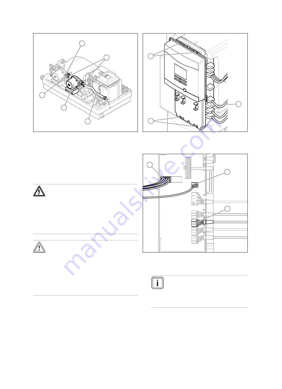
Connect the second solar pump
(6)
and the pipe set
(5,
7)
using flat seals.
–
The arrow on the pump casing must point in the
direction of the long pipe
(5)
.
8.
Tighten the cap nut
(4)
.
9.
Secure the pump with the fastening clamps
(2)
.
6.5.2
Connecting the electrical cables of the
second solar pump
Danger!
Risk of death from electric shock!
A continuous voltage is always present on
the mains connection terminals L and N.
▶
Disconnect the product from the power
mains by de-energising the product using
a partitionb with a contact opening of at
least 3 mm (e.g. fuses or power switches).
Caution.
Risk of damage to the electrical lines as a
result of high temperatures.
The electrical lines may be damaged by the
high temperatures from the solar fluid that
flows through the copper pipes.
▶
Make sure that the electrical lines are
not positioned directly next to the pipes
through which the solar fluid flows.
2
1
1
1.
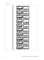
Undo the four bolts
(1)
.
2.
Open the controller casing.
3.
Remove the dummy plugs
(2)
.
X1
X3
X2
X8
X7
X6
X5
X4
eBUS
NL
1
L2
4
5
3
4.
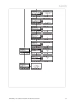
Route the power cable (scope of delivery) of the second
solar pump through the opening in the controller casing
using the cable support sleeve.
Note
For simpler handling, you can completely re-
move the display by removing the plugs from
the X1
(3)
and eBUS
(4)
bushes. Suitable
measures must be taken to prevent electro-
static discharging (ESD).
5.
Insert the power cable plug into the blue bush X6
(5)
in
the solar control.
6.
If necessary, insert the display plug into the X1 bush
(3)
.
7.
If necessary, insert the eBUS plug into the eBUS bush
(4)
.
8.
Close the controller casing.


