background image

8 Start-up

22

Installation and maintenance instructions auroFLOW plus 0020149486_04

Note

All the settings that have been made can be
viewed and changed subsequently under the
menu point

Configuration

.

8.3

Carrying out pressure compensation

Caution.
Risk of damage as a result of incorrect or
incomplete pressure compensation.

Failure to purge the system or purging at a
time other than the one specified, may cause
damage to the solar system. Vaillant accepts
no liability for the correct operation of the
solar system in this instance.

Make sure that the pressure compensa-
tion is carried out as described here, in
particular at the time specified.

The air that is in the collectors is heated up during installa-
tion of the complete solar plant. The density of the air in the
collectors is reduced.

When the solar system is started for the first time, the hot air
leaves the collectors and flows into the much cooler storage
tank of the solar charger, where it cools down. This leads to
negative pressure in the system.

As negative pressure in the solar system can lead to pump
noises and has a negative impact on the power and working
life of the solar pumps, pressure compensation must be car-
ried out at initial start-up.

Note

Once pressure compensation has been per-
formed, it is not necessary to repeat the process,
as long as the solar system is not opened.

Danger!
Risk of personal injury due to incorrect
pressure compensation.

Solar fluid or hot vapour escaping from the
purging valve may cause serious scalding.

The following instruction must be followed
when carrying out the pressure compens-
ation.

1

2

Carry out the pressure compensation immediately after
completing the installation assistant and, if required, re-
peat the procedure once again on that same evening if
the solar plant has cooled down.

Connect a hose that runs down to the floor from the pur-
ging valve

(1)

.

Place the end of the hose in a collecting container suit-
able for storing solar fluid

(2)

. Hold the hose in the col-

lecting container in such a way that air can flow into it.

To ensure that you are sufficiently protected against es-
caping hot vapour and solar fluid, do not immerse the
end of the hose in the solar fluid.

Start the

Test solar circuit filling

check programme.

Menu

Installer level

Test menu

Check pro-

grammes

Test solar circuit filling

At initial start-up of the system, air may collect in/in front of
the solar pumps. To force out the air, it may be necessary
to stop and restart the solar pumps several times. When the
solar pumps are running, noise and vibrations may occur,
however these are harmless.

During the filling mode (solar pump running), wait for 2
minutes.

With the solar pump still running, carefully open the pur-
ging valve.

Some solar fluid may be emitted under pressure from
the hose.

After this, air can be heard being drawn into the solar
system.

Once air has stopped being drawn in after a few
seconds, close the purging valve.

Stop the check programme

Test solar circuit filling

.

Remove the hose from the purging valve.

Содержание auroFLOW plus VPM 15 D

Страница 1: ... instructions auroFLOW plus VPM 15 D VPM 30 D wiring centre BE de DE Installation and maintenance instructions Publisher manufacturer Vaillant GmbH Berghauser Str 40 D 42859 Remscheid Tel 49 21 91 18 0 Fax 49 21 91 18 2810 info vaillant de www vaillant de ...

Страница 2: ...dule 11 6 Installation 12 6 1 Carrying out the hydraulics installation 12 6 2 Carrying out the electrical installation 13 6 3 Completing installation 15 6 4 Installing the expansion module 15 6 5 Installing the second solar pump 16 6 6 Wall mounting the expansion module 18 7 Operation 18 7 1 Operating concept of the solar charger 18 8 Start up 18 8 1 Filling and purging the system 19 8 2 Running t...

Страница 3: ...nce with all inspection and main tenance conditions listed in the instruc tions Any other use that is not specified in these instructions or use beyond that specified in this document shall be considered improper use Any direct commercial or industrial use is also deemed to be improper Caution Improper use of any kind is prohibited 1 3 General safety information 1 3 1 Risk caused by inadequate qua...

Страница 4: ...oring devices have been removed bridged or disabled Immediately rectify any faults and damage that may affect safety At lengths of over 10 m 230 V supply lines must be laid separately from sensor or bus lines 1 3 7 Risk of material damage caused by using an unsuitable tool Use the correct tool to tighten or loosen screw connections 1 3 8 Damage to the environment as a result of leaking solar fluid...

Страница 5: ...uilding as a result of leaking solar fluid Leaking solar fluid may cause damage to the building structure Disconnect the solar charger from the power mains Fix the leaks in the solar system Fill the solar system with solar fluid Switch on the power supply to the solar charger 1 4 Requirements for lines Use standard commercial lines for the wir ing Minimum cross section Supply line 230 V 1 5 mm Sen...

Страница 6: ...fety device and expansion vessel If an auroSTOR is in stalled a safety device and expansion vessel are also re quired between the auroSTOR and solar charger Two diverter valves can be installed in the solar system 1 The UV4 which is connected to the auroMATIC VRS 620 3 First priority allSTOR Second priority Swimming pool or other cylinder 2 The UV5 which is connected to the solar charger Switches ...

Страница 7: ...p 5 Cylinder charging circuit flow sensor 6 Solar pump 7 Solar system expansion relief valve 8 Solar circuit fill and drain connection 9 Cylinder primary pipework 10 Cylinder return 11 Solar fluid storage tank 12 Retainer for front casing screw 13 Solar controller 14 Solar circuit safety temperature monitor 15 Cylinder charging circuit safety temperature monitor 16 Solar return temperature sensor ...

Страница 8: ... instructions auroFLOW plus 0020149486_04 4 2 Design of the auroFLOW plus solar charger basic module and expansion module Note The functional elements of the basic module are described on the previous page 1 2 1 2 Solar fluid storage tank 2 2 Solar pump ...

Страница 9: ...n the identification plate The serial number may also be shown on the product s display Operating instructions 4 6 CE label The CE label shows that the products comply with the basic requirements of the applicable directives as stated on the identification plate The declaration of conformity can be viewed at the manufac turer s site 5 Installation 5 1 Storage conditions Store the product in a dry ...

Страница 10: ...acilitate maintenance we recommend a clearance of 350 mm 5 8 Clearance from combustible components It is not necessary to maintain a clearance between the product and components made of combustible materials that go beyond the minimum clearances 5 9 Mains connection cable The product is fitted in the factory with a mains connection cable that has to be connected up permanently on site If the mains...

Страница 11: ...nstalling the basic module 5 12 1 Removing the front casing A B C D 1 Take hold of the recessed handle at the bottom edge of the white panel 2 Pull the lower edge of the panel forwards and remove the panel by pulling it upwards 3 Undo the bolt 4 Pull the front casing forwards and off 5 12 2 Wall mounting the basic module of the solar charging system Danger Risk of accidents as a result of insuffi ...

Страница 12: ...y be carried out by a competent person Note Seals made of rubber like materials may be subject to plastic deformation which can lead to pressure losses We recommend using seals made of a paste like fibre material 6 1 1 Connecting the cylinder charging circuit Note We recommend that the solar charging system be connected to the cylinder charging circuit us ing service valves The service valves are ...

Страница 13: ...per son who is responsible for complying with the existing standards and directives Caution Risk of damage to the electrical lines as a result of high temperatures The electrical lines may be damaged by the high temperatures from the solar fluid that flows through the copper pipes Make sure that the electrical lines are not positioned directly next to the pipes through which the solar fluid flows ...

Страница 14: ...rrent sensitive RCDs type A or universal RCDs type B with short time delay VSK Connect the product using a fixed connection and a partition with a contact opening of at least 3 mm e g fuses or power switches see Mains connection cable Page 10 6 2 3 Connecting the collector temperature sensor cylinder temperature sensor and system controller Note Only carry out points 6 and 7 if an external system ...

Страница 15: ...p must be installed To connect the two storage tanks the controller bracket and the storage tank of the basic module must first be removed When you need to work on the basic module and the expansion module this work can be made easier if the modules are on the floor Carry out the work steps in this section one after the other and in the exact sequence that is described here 6 4 1 Removing the cont...

Страница 16: ...e connec tion pipes through the openings in the side panel of the casing 6 4 4 Fitting the controller bracket 1 Slide the controller bracket 1 over the pipes until it clicks into place 6 5 Installing the second solar pump 6 5 1 Connecting the hydraulic lines of the second solar pump 2 3 4 1 1 Find the control cable of the second solar pump in the cable harness 3 2 Route the control cable through t...

Страница 17: ...emperatures The electrical lines may be damaged by the high temperatures from the solar fluid that flows through the copper pipes Make sure that the electrical lines are not positioned directly next to the pipes through which the solar fluid flows 2 1 1 1 Undo the four bolts 1 2 Open the controller casing 3 Remove the dummy plugs 2 X1 X3 X2 X8 X7 X6 X5 X4 eBUS N L1 L2 4 5 3 4 Route the power cable...

Страница 18: ...operator level are also described in the operating instructions An overview of the menu structure at the installer level is included in the appendix Page 29 7 1 1 Calling up the installer level Caution Risk of damage caused by incorrect hand ling Incorrect settings at installer level may cause damage to the solar plant You must only access the installer level if you are an approved competent perso...

Страница 19: ...ging circuit using the pressure gauge that is available on site and add extra water as required 6 Check the cylinder charging circuit for leak tightness Conditions The cylinder is an auroSTOR Fill the cylinder charging circuit with suitable heating water Flush out the cylinder thoroughly so that the air can es cape from the pipe coil Check the pressure in the cylinder charging circuit While doing ...

Страница 20: ... is star ted the installation assistant starts again Switch on the power supply to the product 8 2 1 Setting the language Note If a system controller has been connected the language can only be set on the system controller 1 Set the desired language using or 2 Press to confirm the set language 3 Press again to confirm the language a second time and to prevent it being changed unintentionally 8 2 2...

Страница 21: ...on time Page 24 Danger Risk of personal injury due to incorrect pressure compensation Solar fluid or hot vapour escaping from the purging valve may cause serious scalding The following instruction must be followed when carrying out the pressure compens ation If you open the purging valve while the solar pump is running you must do so carefully Some solar fluid may be emitted under pressure from th...

Страница 22: ...pressure compensation Solar fluid or hot vapour escaping from the purging valve may cause serious scalding The following instruction must be followed when carrying out the pressure compens ation 1 2 Carry out the pressure compensation immediately after completing the installation assistant and if required re peat the procedure once again on that same evening if the solar plant has cooled down Conn...

Страница 23: ...Configuration to subsequently change the settings that have been made using the installation assistant Language Contact details Date Time Summer winter time Cascade Number of collectors In addition the following information can be set or read Filling time correction Mode Heating flow set target temperature Hot water set target temperature Shift load switching valve switch temperature Maximum cylin...

Страница 24: ...ps may suck in air To prevent this the two solar pumps are started up separately During the first stage only the lower solar pump is running You can use the Compensa tion time setting to adjust the length of the first stage Set the compensation time so that the solar fluid level is approx imately 5 cm in both storage tanks before the second solar pump is activated 8 5 10 Software version Menu Inst...

Страница 25: ...llector fastenings and connections Annually Inspection and maintenance work Interval Check that the brackets and collector com ponents are clean and fitted properly Annually Check the pipe insulations for damage Annually Solar controller Check the pump function Annually Check the sensor temperature display Annually Check the solar yield for plausibility Annually Check the filling loop Annually Cyl...

Страница 26: ...ometer 11 5 2 Draining the solar fluid Preliminary work Switch off the solar system by interrupting the power supply 3 1 2 1 Connect a hose that runs down to the floor from the purging valve 1 2 Place the end of the hose in a collecting container that is suitable for storing solar fluid 2 and which has suf ficient capacity 20 l or 40 l capacity Hold the hose in the collecting container in such a w...

Страница 27: ...devices Close all available isolator devices in the cylinder char ging circuit on site 12 2 Permanently decommissioning the product 12 2 1 Switching off the solar charging system Disconnect the product by de energising it using a parti tion with a contact opening of at least 3 mm e g fuses or power switches 12 2 2 Completely draining the solar and heating installation 1 Completely drain the heatin...

Страница 28: ... auroFLOW plus 0020149486_04 B 1620 Drogenbos Belgien Belgique België Kundendienst Service après vente Klantendienst 2 3349352 Applicability Germany Vaillant Profi Hotline 018 06 999120 20 Cent Anruf aus dem deutschen Festnetz aus dem Mobilfunknetz max 60 Cent Anruf ...

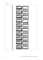
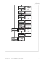
Страница 29: ... P 07 Back Test solar circuit filling Select T 40 Back T1 temperature sensor 14 1 C Test menu Back Select Statistics Check programmes Sensor actuator test P 07 Cancel Test solar circuit filling Test active Statistics Cylinder charge pump Back Select Solar pump Solar pump 2 Solar pump 2 Back Operating hours 20 Statistics Cylinder charge pump Back Select Solar pump Solar pump 2 Cylinder charge pump ...

Страница 30: ...of collectors Filling time corr Back 0 Filling time corr Configuration Back Select Filling time corr Operating mode Heating temperature Back Target temperature of heating flow 0 Configuration Back Select Number of collectors Filling time corr Operating mode Back Automatic Configuration Back Select Operating mode Heating temperature DHW temp Back Target temperature of domestic hot water 0 DHW temp ...

Страница 31: ...istant press OK OK Configuration Back Select Max cylinder temp Switch on diff eBUS controller Back Not detected eBUS controller Configuration Back Select Switch on diff eBUS controller Filling power Back 0 Filling power Configuration Back Select eBUS controller Filling power Compensation time Back 0 Compensation time Configuration Back Select Filling power Compensation time Software version Back S...

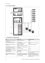
Страница 32: ...min Check the solar circuit for siphons Cylinder charging pump is running how ever the solar pump is not running Overrun function solar charging stopped shortly before No fault Cylinder charging pump running at low outside temperatures Frost protection function No fault Collector temperature very high and solar system starts filling Hot starts are possible as a result of Drain back technology No f...

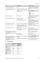
Страница 33: ...wing of the storage tank is normal very strong rapid discolouration is an in dication of high temperatures in the solar circuit Check the solar circuit function Check the cylinder charging circuit function The solar fluid level falls over time Solar circuit leaking Find and seal any leaks Pressure too high and expansion relief valve discharges Check the expansion relief valve function Check that t...

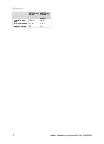
Страница 34: ...on and maintenance instructions auroFLOW plus 0020149486_04 VPM 15 D basic module VPM 30 D ba sic module with expansion module Product dimensions depth 340 mm 340 mm Collector surface area 15 m 30 m Number of collectors 6 12 ...

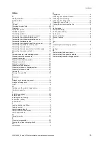
Страница 35: ... charging system 27 Disposing of the solar fluid 27 Documents 6 Draining the solar fluid 26 E Electricity 3 F Filling the cylinder charging circuit 19 Filling the storage tank 19 Frost 4 H Handing over the solar charging system 24 Hand over operator 24 I Installation assistant 20 Installer level 18 Installing the front casing 15 Instructions validity 6 Intended use 3 L Leaking heating installation...

Страница 36: ...Telefax 021 91 18 2810 Vaillant Profi Hotline 018 06 999120 20 Cent Anruf aus dem deutschen Festnetz aus dem Mobilfunknetz max 60 Cent Anruf Vaillant Kundendienst 018 06 999150 20 Cent Anruf aus dem deutschen Festnetz aus dem Mobilfunknetz max 60 Cent Anruf info vaillant de www vaillant de These instructions or parts thereof are protected by copyright and may be reproduced or distributed only with...

Отзывы: