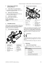
5 Installation
14
Installation instructions 0020230738 0020230756_00
–
Recommended tightening torque:
≤
1.9 Nm
5.
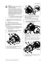
Use the PG screwed connection to secure the cable.
–
Recommended tightening torque:
≤
6.0 Nm
6.
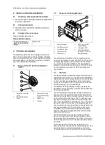
Fit the rotary knob
(4)
on the setting control.
5.6
Installing the Energy Manager
In accordance with its classification into overvoltage cat-
egory III, the Energy Manager must only be connected in
the sub-distribution or electric circuit distribution on the con-
sumer side downstream of the energy supply company's
energy counter.
The Energy Manager must only be installed in approved
buildings or electric distributors, meaning that the connec-
tions for the outer and neutral conductors are located down-
stream of a cover or touch protection.
The Energy Manager is supplied with power via the outer
conductor L1. As a minimum, the outer conductor L1 and the
neutral conductor N must be connected so that the unit can
be switched on.
The fuse protection must not exceed 32 A. Use an external
current transformer for higher currents.
The Energy Manager must be connected to lines with a
cross-section of at least 10 mm
²
and whose length must not
exceed 1 m.
The end user must be able to switch off the Energy Manager
so that it is voltage-free using a freely accessible counter
fuse or an additional off switch.
Before carrying out any installation and/or maintenance
work, switch off the electric distributor so that it is voltage-
free, and secure it against being unintentionally switched
back on again.
If you want to permanently route a network cable, comply
with the stipulated minimum clearances between the network
cable and the mains-voltage-carrying installation compon-
ents or use suitable insulation.
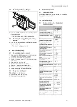
▶
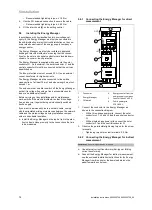
Install the Energy Manager on the top hat rail in the elec-
tronics box in close proximity to the connections that are
to be measured.
5.6.1
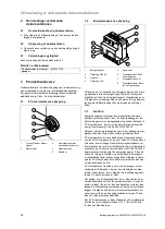
Connecting the Energy Manager for direct
measurement
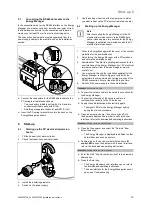
L1
L1
L2
L2
L3
L3
L1
L1
L2
L2
L3
L3
N
L1
Reset
OUT
L2 L3
IN
L1 L2 L3 N
L1 L2 L3
L1 L2 L3 N
2
3
4
5
1
6
1
Consumer
2
Energy Manager
3
Off switch
4
Energy counter from the
energy supply company
5
Counter fuses 3 x 63 A
6
Public power grid
230 V/400 V
1.
Connect the conductor to the Energy Manager as
shown in the connection diagram.
–
With a three-phase power grid, connect the outer
conductors L1, L2 and L3 and the neutral conductor
N.
–
With a single-phase power grid, connect the outer
conductor L1 and the neutral conductor N.
2.
Observe the permissible tightening torque for the screw
terminals.
–
Tightening torque for screw terminals: 2.0 Nm
5.6.2
Connecting the Energy Manager for indirect
measurement
Conditions
: Currents higher than 63 A present
▶
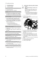
Use external current transformers (bar-type or folding
current transformer).
▶
Connect the Energy Manager for indirect measurement;
see the enclosed installation instructions for the Energy
Manager from B-control or the download area on the
website www.b-control.com.

