Installation 5
0020233500_01 auroCOMPACT Installation and maintenance instructions
13
5.2
Checking the gas meter
▶
Make sure that the existing gas meter is capable of
passing the rate of gas supply required.
5.3
Gas and water connections
Caution.
Risk of material damage due to the gas
leak-tightness test.
At a test pressure of >11 kPa (110 mbar), gas
leak-tightness tests may cause damage to
the gas valve.
▶
If, during gas leak-tightness tests, you
also place the gas lines and the gas valve
in the product under pressure, use a max.
test pressure of 11 kPa (110 mbar).
▶
If you cannot limit the test pressure to
11 kPa (110 mbar), close any gas isolator
cocks that are installed upstream from the
product before you carry out the gas leak-
tightness test.
▶
If, during gas leak-tightness tests, you
have closed the gas isolator cock that is
installed upstream of the product, relieve
the gas line pressure before you open this
gas isolator cock.
Caution.
Risk of material damage caused by corro-
sion
Due to non-diffusion-tight plastic pipes in the
heating installation, air gets into the heating
water. Air in the heating water causes corro-
sion in the heat generator circuit and in the
product.
▶
If you use non-diffusion-tight plastic pipes
in the heating installation, ensure that no
air gets into the heat generator circuit.
Note
In order to keep heat losses to a minimum, we re-
commend that you provide the water pipe spigots
to the floor-standing boiler outlet and to the install-
ation with heat insulation.
1.
Check that the volumetric capacity of the expansion
vessel is sufficient for the system volume.
◁
If the volume of the expansion vessel is insufficient
for the installation, install an additional expansion
vessel, connected as close to the product as pos-
sible, in the heating return.
2.
Install an expansion relief valve and a stopcock on the
heating return.
3.
Install a domestic hot water safety group and a stop-
cock on the cold water pipe.
4.
Install a filling device between the cold water pipe and
the heating flow.
5.
Install a stopcock on the heating flow.
6.
Install a stopcock on the gas pipe.
7.
Blow or flush the supply pipes thoroughly prior to install-
ation.
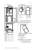
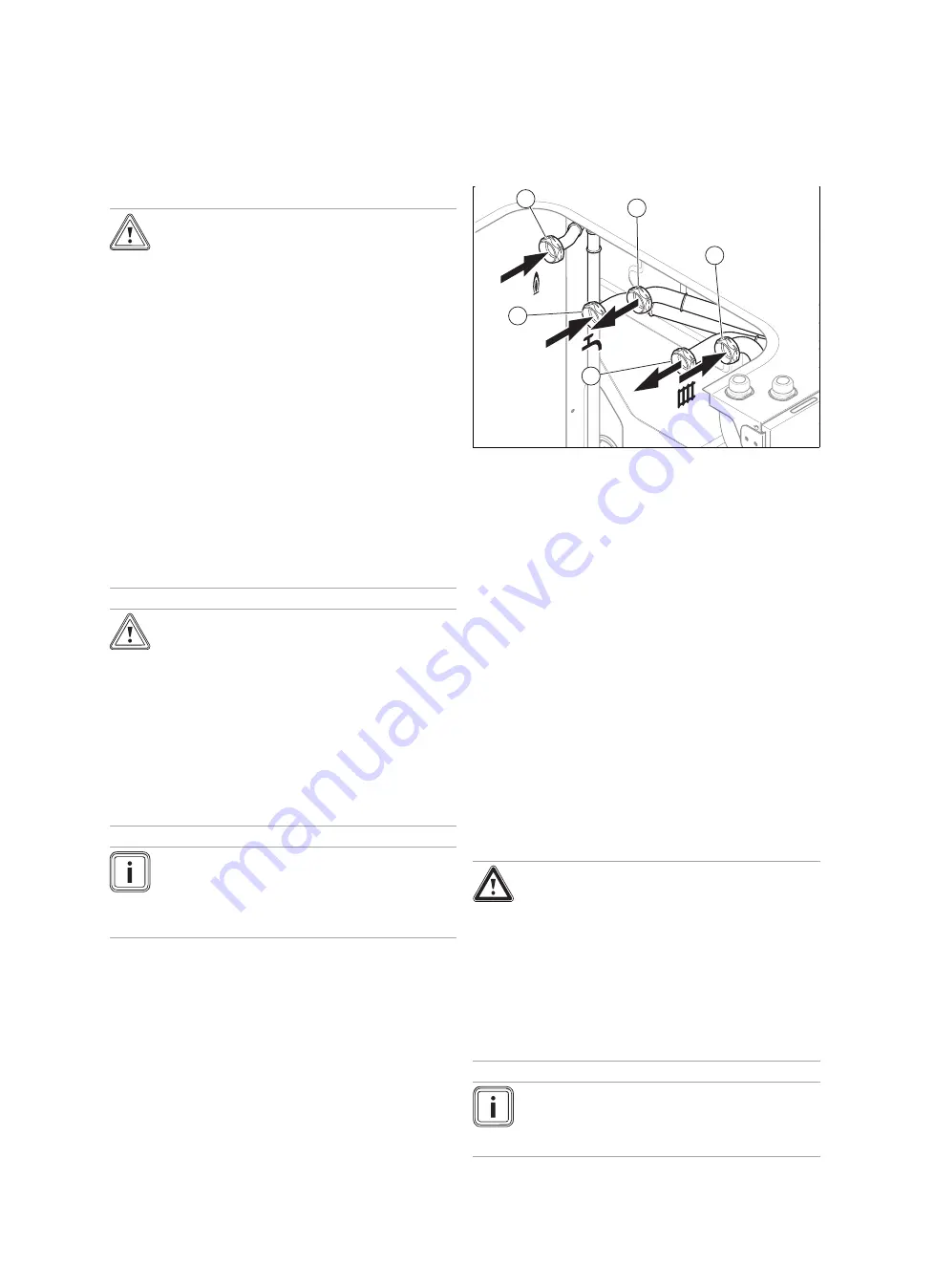
2
3
4
5
1
1
Gas connection, G3/4
2
Hot water connection,
G3/4
3
Heating return connec-
tion, G3/4
4
Heating flow connec-
tion, G3/4
5
Connection for the cold
water supply line, G3/4
8.
Connect the water and gas connections in accordance
with the applicable standards.
–
Loss of pressure between the gas meter and the
product:
≤
1 mbar
9.
Purge the gas pipe before start-up.
10. Check whether the connections (
→
Page 27) are leak-
tight.
11. Water can escape from the expansion relief valve. You
should therefore ensure that the drain hose opposite
the outdoor air remains open.
12. Actuate the drainage device on the expansion relief
valve regularly in order to remove any scale deposition
and ensure that the device is not blocked.
5.3.1
Checking the gas line for leak-tightness
▶
Check the entire gas line properly for leak-tightness.
5.4
Connecting the condensate drain pipework
Danger!
Risk of death from escaping flue gases!
The siphon's condensate drain pipework
must not be connected to waste-water piping
because, otherwise, the internal condensate
siphon may be drained fully and flue gas may
escape.
▶
Do not connect the condensate drain
pipework tightly to the waste-water pip-
ing.
Note
Follow the instructions listed here and observe
directives and local regulations on condensed
water discharge.


