RD 300-450 F
Ver.1.3 07/06/01
99
6.3.1
Some functions of the Control Box
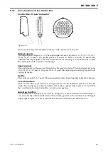
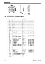
Control Box 37-pole connector
Figure 6.6
The location of the poles is marked on the face of the connector, see Fig 6.3.
Output signals
The output signal voltage is +12 V. The output signals are sent via poles 12, 13, 14, 15, 25, 26, 27,
28, 29, 30, 31, 32 and 33. The parallel poles are 12 and 25, 13 and 26, 14 and 27, 15 and 28. The
conditions for output signals to be released are that the feed housing is not shut off at the Control
Box and that the drill is under Low lift height.
Input signals
The input signals are the same as the earths for the respective poles. The input signals are poles
10,16, 20, 21, 22, 23 and 24. For poles 20, 22, 23 and 24 the input signal is earthing repeated with
varying frequency.
Earths
The earths are poles 5, 6, 7 and 8. These are parallel and are bound together in the cable harness.
Low lift function
The Low lift switch on the drill sends an input signal to the lift transmitter (pole 21) at Low lift
height. The internal logic in the Control Box then sends an output signal to poles 31, 30 and 29 if
the Low lift switch on the Control Box is in the centre position.
Autostep function
Provided that the Control box is set correctly, changeover of the bout markers and tramlining oc-
curs automatically when the drill is raised from working position to the minimum Low lift height
(input signal on pole 21). This occurs whether the seed feed housing are shut off or not.
Содержание RAPID RD F Series
Страница 1: ...Ver 1 3 07 06 01 900107 en Instructions Seed drill RAPID series RD 300 450 F No 10 026 11 999...
Страница 2: ...2 Ver 1 3 07 06 01...
Страница 6: ...6 Ver 1 3 07 06 01...
Страница 16: ...Assembly instructions 16 Ver 07 06 01 07 06 01...
Страница 23: ...RD 300 450 F Ver 1 3 07 06 01 23...
Страница 41: ...RD 300 450 F Ver 1 3 07 06 01 41...
Страница 47: ...RD 300 450 F Ver 1 3 07 06 01 47...
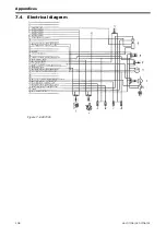
Страница 108: ...Appendices 108 Ver 07 06 01 07 06 01 7 4 Electrical diagram Figure 7 8 307335...

