


CeilingVIEW HD-18 DocCAM Series
CeilingVIEW HD-18 DocCAM Manual - Document Number 342-0195 Rev. B
12 of 24
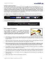
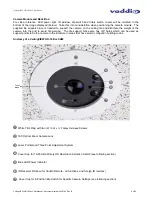
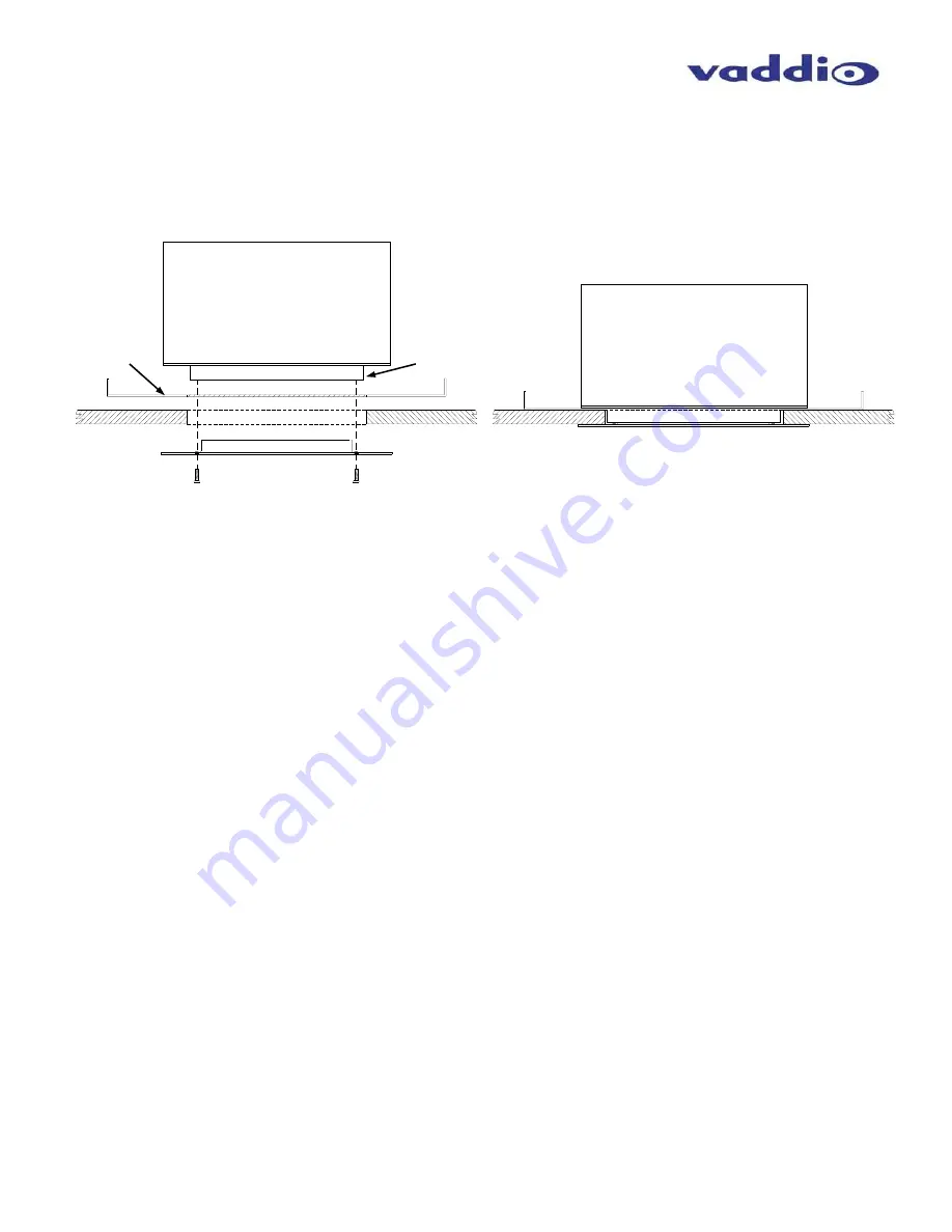
Step 5:
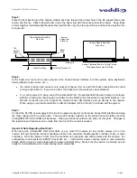
Place the front bezel ring of the camera module back box through the circular hole in the tile support brace (see
below) and the tile. Attach the white trim ring to the bezel ring with the white screws from below. Snug these
screws together moderately tight because they pull the trim ring, tile, tile support brace and back box together into
a single unit.
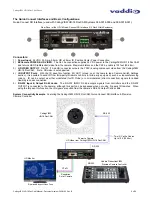
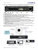
Step 6:
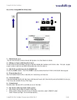
At the head end, connect the video outputs of the Quick-Connect Interface into the systems video destination
device (display, codec, mixer, etc ).
x
If a codec is being used, make sure to properly configure it for use with the chosen resolution and control
port type and reboot it. If you don’t reboot, the codec won’t know what you have attached.
x
If a control system is being used (ProductionVIEW HD, ProductionVIEW Precision Camera Controller,
AMX® or Crestron®), then plug the controller into the RS-232 IN of the Quick-Connect SR Interface. The
RS-232 connection can also bypass the Quick-Connect SR Interface and go directly to the camera.
When using a non-Vaddio controller, an RS-232 adapter (9-Pin to RJ-45) is included with the system.
Step 7:
Connect the 24 VDC power supply’s DC side to the power connector on the Quick-Connect SR Interface and plug
the high voltage side into a wall outlet. The blue LED Power indicator on the Quick-Connect Interface and the
CeilingVIEW HD-18 DocCAM will illuminate. Video and control should also be active at this point. Changes to
the resolution and functions can be made from the front of the camera if needed.
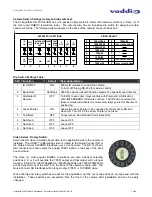
Important Note Regarding Boot Order:
When using the CeilingVIEW HD-18 DocCAM, or any other PTZ camera for that matter, always turn on the
camera first with the Quick-Connect Interface and then the controller (Vaddio joystick controller, codec or other
controller). With the camera on first, then the controller can recognize and communicate with the camera. For
configurable control systems (AMX®, Crestron®, etc ) with master power controls, build in communication
delays before trying to communicate with the camera straight away. Make sure the camera is powered up and
ready for communication prior to bombarding it with commands.
Camera Module Back Box
Side View
Camera Module Back Box
Side View
Tile
Support
Brace
Ceiling Tile
White Trim Ring
FH White Screws X 2
System Tightened Down to Ceiling Tile and
Tile Support Brace with Trim Ring
System
Component
Stack-up
Bezel
Ring