
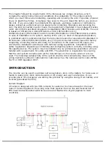


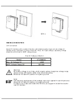


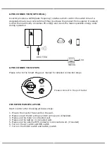


GRID CONNECTION
VT series inverter are designed for single phase grid. Voltage is 220/230/240V, frequency
is 50/60Hz. Other technical requests should comply with the requirement of the local
public grid.
Micro-breaker should be installed between inverter and grid, any load should not be connect
-
ed with inverter directly.
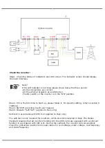
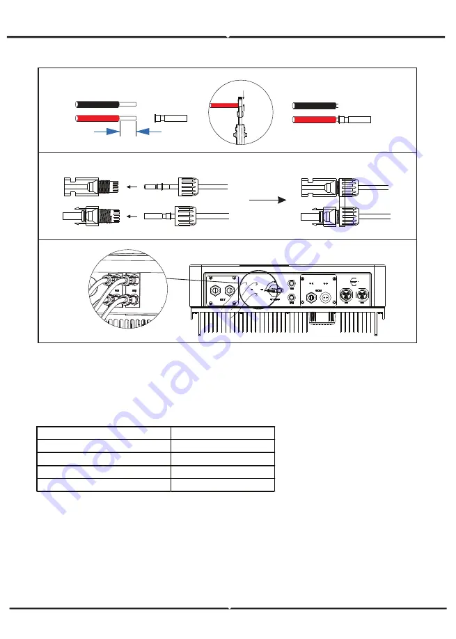
CONNECTION STEPS
Step 1. Check the grid voltage.
1.Check the grid voltage and compare with the permissive voltage range
(Please refer to technical data).
2.Disconnect the circuit board from all the phases and secure against re-connection.
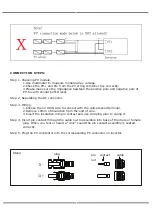
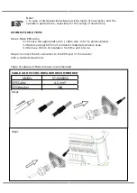
10mm
Crimp!
12AWG
insert
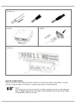
Step3
Step4
Step5
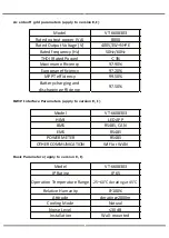
Table of cable and Micro-breaker recommended
MODEL
VT-6608303
E VERSION CABLE
4-5 mm²
E VERSION MICRO-BREAKER
20A
I VERSION CABLE
6-8mm²
I VERSION MICRO-BREAKER
40A
Содержание VT-6608303
Страница 32: ...8 1 2 PV2 input display interface 8 1 3 Bus voltage 8 1 5 BMS parameters 8 1 6 BMS parameters 8 1 4 Battery...
Страница 33: ...8 1 7 Grid connected output 8 1 8 Inverter output 8 1 9 Load 8 1 10 Power...
Страница 34: ...8 1 11 Power 8 1 12 Temperature 8 1 13 Status information 8 1 14 Error information...
Страница 36: ...8 2 Setting 8 2 1 System setting...
Страница 37: ......
Страница 38: ......
Страница 39: ...8 2 2 BAT Setting...
Страница 40: ......
Страница 41: ...8 2 3 Grid standard...
Страница 42: ...8 2 4 System setting...
Страница 43: ......
Страница 44: ......
Страница 45: ...8 2 5 485 Address 8 2 6 485 Baud rate 8 2 7 Language...
Страница 46: ...8 2 8 LCD backlight 8 2 9 Date time 8 2 10 Clear history...
Страница 47: ...8 2 11 Password Setting 8 2 12 Maintenance 8 2 13 Factory reset 8 2 14 Inquiry...
Страница 48: ......
Страница 49: ...8 2 12 Statistics...
Страница 50: ......
Страница 52: ......
Страница 53: ......
Страница 54: ......


