

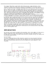

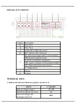


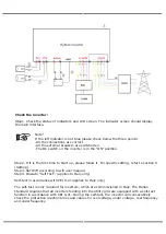


CONNECTION STEPS:
Step 1. Checking PV module.
1.Use multimeter to measure module array voltage.
2.Check the PV+ and PV- from the PV string combiner box correctly.
3.Please make sure the impedance bewteen the positive pole and negative pole of
PV to earth should be MΩ level.
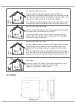
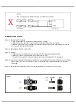
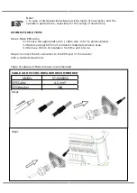
Step 2. Separating the DC connector.
Step 3. Wiring.
1.Choose the 12 AWG wire to connect with the cold-pressed terminal.
2.Remove 10mm of insulation from the end of wire.
3.Insert the insulation into pin contact and use crimping plier to clamp it.
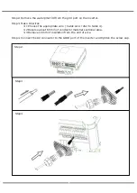
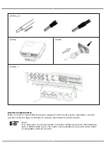
Step 4. Insert pin contact through the cable nut to assemble into back of the male or female
plug. When you feel or heard a "click" sound the pin contact assembly is seated
correctly.
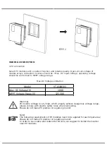
Step 5. Plug the PV conntector into the corresponding PV connector on inverter.
plug
pin contact
cable
nut
Step2
Содержание VT-6608303
Страница 32: ...8 1 2 PV2 input display interface 8 1 3 Bus voltage 8 1 5 BMS parameters 8 1 6 BMS parameters 8 1 4 Battery...
Страница 33: ...8 1 7 Grid connected output 8 1 8 Inverter output 8 1 9 Load 8 1 10 Power...
Страница 34: ...8 1 11 Power 8 1 12 Temperature 8 1 13 Status information 8 1 14 Error information...
Страница 36: ...8 2 Setting 8 2 1 System setting...
Страница 37: ......
Страница 38: ......
Страница 39: ...8 2 2 BAT Setting...
Страница 40: ......
Страница 41: ...8 2 3 Grid standard...
Страница 42: ...8 2 4 System setting...
Страница 43: ......
Страница 44: ......
Страница 45: ...8 2 5 485 Address 8 2 6 485 Baud rate 8 2 7 Language...
Страница 46: ...8 2 8 LCD backlight 8 2 9 Date time 8 2 10 Clear history...
Страница 47: ...8 2 11 Password Setting 8 2 12 Maintenance 8 2 13 Factory reset 8 2 14 Inquiry...
Страница 48: ......
Страница 49: ...8 2 12 Statistics...
Страница 50: ......
Страница 52: ......
Страница 53: ......
Страница 54: ......


