


P/N 1070341 • REV 2.0 • ISS 22FEB11
9 / 56
EN: Installation Sheet
Description
This manual provides information for the following four-door
access control data gathering panel (DGP): ATS1251,
ATS1252, ATS1253 and ATS1254. When referring to the four-
door DGP, this can be read as any variant of the ATS125x,
unless specifically stated otherwise.
Table 1: List of existing four-door DGP variants
Variant Auxiliary
power
Locks
power
Housing Dimensions
ATS1251 12
V 12
V
ATS1642 (big)
480x464x160 mm
ATS1252 12
V 24
V * ATS1642 (big)
480x464x160 mm
ATS1253 12
V 12
V
ATS1640 (small) 445x315x90 mm
ATS1254 12
V 24
V * ATS1640 (small) 445x315x90 mm
* In case of 24 VDC variant always use 2 batteries in series.
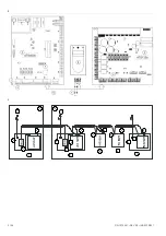
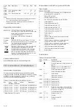
ATS125x four-door DGP overview
Figure 1 legend
Item Description
1.
DIP switches (see “DIP switch settings” on page 12).
2.
RAM or IUM (optional).
3. EPROM
(factory
fitted).
4.
KILL jumper - Factory default ATS125x when shorted.
5.
Battery fuse F1.
6.
Auxiliary power fuse F2.
7.
Databus 1 fuse F3.
8.
Databus 2 fuse F4.
9.
Lock power 1 fuse F5.
10.
Lock power 2 fuse F6.
11.
Siren / switch fuse F7
12. L1-L4
LED
13.
TERM 1. Use this link to terminate the system databus.
14.
TERM 2. Use this link to terminate the local databus,
connection 1 on terminal CON9.
15.
TERM 3. Use this link to terminate the local databus,
connection 2 on terminal CON10.
16.
CON14 Input expander connector
17.
CON15 Output expander connecter
18. Mains
terminal
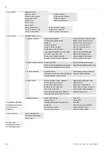
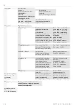
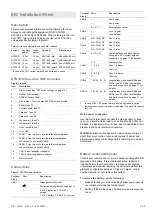
Connections
Table 2: ATS125x connections
Terminal
block
Wire Description
CON1
,
Mains power connection
System earth (see details on page 11).
+,
−
2 x 12 V batteries, 7.2 Ah (24 V
version)*
1 x 12 V battery, 7.2 Ah (12 V version)
Terminal
block
Wire Description
CON2 +,
−
Aux.
power
+,
−
Aux.
power
S+,
S
−
**
External siren output
CON3 +,
−
Lock 1 power
+,
−
Lock 2 power
CON4
NO, COM, NC
Door 1 relay
NO, COM, NC
Door 2 relay
CON5
NO, COM, NC
Door 3 relay
NO, COM, NC
Door 4 relay
CON6
0V, D+, D
−
System databus and panel tamper
wiring (see “ATS system databus
connection” on page 11 for details).
T, C
Tamper switch
CON7
1, 2, 3, 4
Zone 1-4 inputs
C
Common
CON8
5, 6, 7, 8
Zone 5-8 inputs
C
Common
CON9
12V, 0V, D+, D
−
Local databus to connect RASs and
DGPs (see “ATS125x local databus
and earth connection” on page 11 for
details).
CON10
12V, 0V, D+, D
−
Local databus to connect RASs and
DGPs (see “ATS125x local databus
and earth connection” on page 11 for
details).
*
In case of 24 VDC variant always use two batteries in series.
**
External siren output is a supervised output. Typical EOL resistor
is 1 k
.
Mains power connection
Use the mains terminal to connect the mains-supply. A fixed
cable, or a flexible mains lead to an earthed mains outlet, can
be used. In case fixed wiring is used, insert a dedicated circuit
breaker in the power distribution network.
WARNING:
Electrocution hazard. To avoid personal injury or
death from electrocution, remove all sources of power and
allow stored energy to discharge before installing or removing
equipment.
Battery removal/disposal
This product contains one (or more) sealed, rechargeable, BS-
type lead-acid battery. It is a maintenance-free, leakproof,
long-life battery that should not be removed under normal
circumstances. Because removing the battery may affect the
product's configuration settings or trigger an alarm, only a
qualified installer should remove the battery.
To remove the battery, do the following:
1. Make sure that your product settings allow you to open its
cover without starting the tamper alarm.
2. Switch off the mains power, if necessary, and remove the
cover.
Содержание Interlogix ATS125 Series
Страница 56: ...56 56 P N 1070341 REV 2 0 ISS 22FEB11 ...