


P/N 1070341 • REV 2.0 • ISS 22FEB11
13 / 56
Door numbering
Door numbers are determined by:
•
The RAS or reader address when connected to the ATS
system databus (doors 1 to 16).
•
Four-door DGP address (doors 17 to 64).
Doors 1 to 16 are reserved for RAS 1 to 16 and are connected
to the ATS system databus. These only provide basic access
control (door opening).
Doors 17 to 64 are used for door numbers and are controlled
by a four-door DGP (ATS125x). These doors provide
enhanced access control functions (anti-passback, etc).
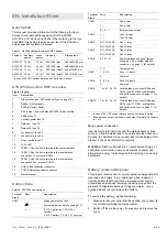
Table 8: Door numbers allocated per DGP
Device address
Door number
RAS 1 to 16
1 to 16 (door open only)
1 2 3 4
DGP
1
17 18 19 20
DGP
2
21 22 23 24
DGP
3
25 26 27 28
DGP
4
29 30 31 32
DGP
5
33 34 35 36
DGP
6
37 38 39 40
DGP
7
41 42 43 44
DGP
8
45 46 47 48
DGP
9
49 50 51 52
DGP
10
53 54 55 56
DGP
11
57 58 59 60
DGP
12
61 62 63 64
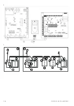
Power-up procedure
When the installation is complete, ensure that the unit is
addressed correctly using DIP switches 1 to 4 (1 to 12 are
available).
Check if the RAM memory in the ATS125x and the Advisor
Master control panel is the same.
On initial power-up, the LEDs on the four-door DGP should
indicate as follows:
• RST
LED:
Off.
ATS system databus indicator LEDs:
•
Rx1: Flashes if the ATS125x receives polling from the
ATS control panel.
•
Tx1: Off if the ATS125x is not addressed or is not
programmed to be polled by the control panel.
Four-door DGP local databus indicator LEDs:
•
Tx: Flashes when the ATS125x is polling remote devices
(readers/interfaces) on the local databus; TX should
always be active.
•
Rx: Flashing indicates remote devices reply to polling.
Setup procedure
The minimal setup only consists of settings required to activate
the DGP and the connected RASs for programming.
1. Set addresses of RASs (readers or keypads) connected to
the local databus of the four-door DGP
2. In the Advisor Master control panel, installer programming
(menu 19.4): DGP, activate polling for the four-door DGP
and set the DGP type.
How to access the ATS125x programming menu
Access to the Door programming menu is via the Advisor
Master,
Installer menu 28, “To remote devices”. When
programming in the four-door programming menu, you are
actually programming the ATS125x.
If you are denied access to “To remote devices”, it is because
one or more of the above hardware or programming criteria
have not been met.
1. The display shows:
Remote Device: 1-DGP, 2-RAS
Device:
Enter the type of remote device you wish to program.
Select 1 (DGP).
2. Enter the number of the remote device you wish to
program. The DGP number is the same as the DGP
address.
Remote DGP Setup
DGP No.:
The following is briefly displayed:
Connecting…
Enter to Abort
You have now accessed the ATS125x Programming menu
for the ATS125x that you have selected. The display
shows the four-door programming menu display:
“#” –Move On “*” Move back
Menu:
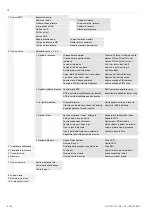
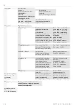
ATS125x programming menus
# Menu
Description
1.
DGP Options
Global options valid for all doors of the
selected four-door DGP.
2. Door
Options
Options
valid for each individual door
on the ATS125x.
3.
Initialise Database
Allows initialisation of door database.
Resets all data in the DGP to default.
4.
Display Card
Displays card details on LCD for the
last card that is badged.
5.
Door Groups
Allows door group details to be viewed.
6. Reserved
7.
System Options
Allows ATS125x outputs to be
activated to indicate system faults on
the ATS125x.
8. Program
Macro
Logic
Enables outputs and internal events to
be generated by logic functions using
ATS125x events.
9.
Version Number
ATS125x firmware and CPLD version
number.
Содержание Interlogix ATS125 Series
Страница 56: ...56 56 P N 1070341 REV 2 0 ISS 22FEB11 ...