


P/N 1070341 • REV 2.0 • ISS 22FEB11
15 / 56
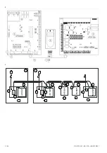
F3: Local databus 1
800 mA, Fast 20x5
F4: Local databus 2
800 mA, Fast 20x5
F5: Lock power 1
2 A, Fast 20x5
F6: Lock power 2
2 A, Fast 20x5
F7: Switched power
1A, Fast 20x5
Mains*: Mains fuse
800 mA, Slow 20x5
*Mains fuse is part of the mains terminal block.
WARNING:
Before removing the mains fuse, the mains power
must be disconnected! See “Mains power connection” on page
9.
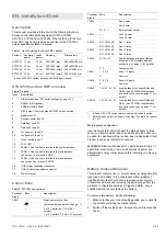
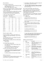
Auxiliary current and battery capacity
Note:
This is only a reference to approval requirements.
Please contact your local sales office for more information
about valid certification.
Table 9: 12 V variants auxiliary current and battery capacity
Approval
grade
Discharge
time (h)
Charge
time (h)
Max Available Auxiliary
Current (mA)
Battery Type:* 7.2Ah
18Ah
26Ah
EN 1&2
12
72
450
1300
1800
EN 3&4
60
24
=
175
290
NF&A2P-2
36
30
=
330
500
NF&A2P-3
72
30
=
110
200
VdS-B
30
24
110
450
700
VdS-C
60
24
=
175
290
* Available battery capacities depend on the housing as well. Please
refer to max. battery capacity in Table 1 on page 9.
Table 10: 24 V variants auxiliary current and battery capacity
Approval
grade
Discharge
time (h)
Charge
time (h)
Max Available Auxiliary
Current (mA)
Battery Type:* 2 x
7.2Ah
2 x
18Ah
2 x
26Ah
EN 1&2
12
72
500
1400
1800
EN 3&4
60
24
=
200
300
NF&A2P-2
36
30
100
400
600
NF&A2P-3
72
30
=
150
250
VdS-B
30
24
120
500
730
VdS-C
60
24
=
200
300
* Available battery capacities depend on the housing as well. Please
refer to max. battery capacity in Table 1 on page 9.
All Auxiliary currents mentioned in the tables above are
calculated for the 24 V auxiliary. For calculation of the
maximum load on 12 V auxiliary outputs a correction factor of
1.6 should be taken into account.
Formula: I
aux
at 12 V = I
aux
at 24 V x 1.6
Example 1:
One wants to meet Approval grade EN 1&2 with two 18 Ah
batteries. The application has a maximum load of 24 V Locks
of 800 mA. According Table 10 above it means that the max
available auxiliary current is 1400 mA at 24 V.
This means that besides the 800 mA for the 24 Locks either:
•
1400 – 800 = 600 mA is left at 24 V Aux, or
•
600 x 1.6 = 960 mA left at 12 V Aux i.e. AUX power,
Locale Comms.
Example 2:
One wants to meet Approval grade NF&A2P-2 with two 18 Ah
batteries. The application has a maximum Local Comms load
(12 V) of 200 mA. According Table 10 above it means that the
max available auxiliary current is 400 mA at 24 V.
This 200 mA at 12 V Local Comms load results in:
•
200 / 1.6 = 125 mA at 24 V, and this leaves
•
400 – 125 = 275 mA @24 V for Aux (i.e. Locks power).
Restrictions:
•
Max 12 V Aux current: 1000 mA.
•
Max 24 V Aux current: 1600 mA.
Maximum auxiliary current can be limited by:
• Discharge
duration
•
Available charge capacity for battery
• Auxiliary
fuse
All data based on board without external equipment.
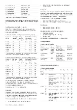
Cabling distance
Table 11: Cabling distance
From To
Distance
Cable
type
ATS control panel
system databus
(J10)
ATS125x
system
databus
(CON6)
1.5 km (total
databus length
without repeaters)
WCAT 52 or
equivalent
Local databus 1
(CON9)
RAS
1.5 km (total
databus length
without repeaters)
WCAT 52 or
equivalent
Local databus 2
(CON10)
RAS
1.5 km (total
databus length
without repeaters)
WCAT 52 or
equivalent
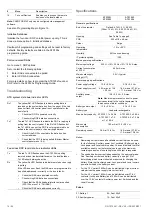
External terminals specification
Table 12: External terminals
Termi-
nal
block
Wire Description
Min Typ Max Unit
CON1
,
AC
transformer
connection
— 20
120
— VAC
VA
+,
−
Battery connection 12V
variant (ATS1251,
ATS1253)
13.6 13.8
7.2
14.0
25
V
Ah
Battery connection 24V
variant (ATS1252,
ATS1254)
27.4 27.6
2 x 7.2
27.8
2 x 25
V
Ah
CON2 +,
−
,
+,
−
Auxiliary power output
13.6 13.8
14.0
2
V
A
S+,
S
−
External siren output
13.6 13.8
14.0
1
V
A
CON3 +,
−
,
+,
−
Lock power output 12V
variant (ATS1251,
ATS1253)
13.6 13.8 14.0
2
V
A
Lock power output 24V
variant (ATS1252,
ATS1254)
27.4 27.6 27.8
2
V
A
Содержание Interlogix ATS125 Series
Страница 56: ...56 56 P N 1070341 REV 2 0 ISS 22FEB11 ...