


12 / 56
P/N 1070341 • REV 2.0 • ISS 22FEB11
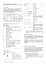
DIP switch settings
DIP switches 1 to 4 (DGP address) are used to identify this
DGP to the Advisor Master control panel, i.e. Assign the DGP
address. A four-door DGP can only be addressed, as DGPs 1
to 12. See Figure 4.
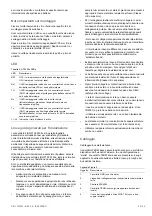
DIP switches 5 and 6 are used for zone expansion
configuration.
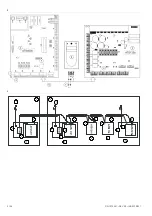
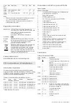
Figure 6 legend
Item Description
1.
8 onboard inputs (no expanders)
2.
8 onboard 1xATS1202
3.
8 onboard 2xATS1202
4.
8 onboard 3xATS1202
DIP switches 7 and 8 are not used.
Zones, RASs and outputs
Numbering
All DGPs, zones, RASs and outputs are numbered according
to a set formula. This is used when determining the physical
numbers/locations of DGPs, outputs etc. during programming.
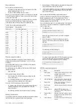
Table 5: Zones, RASs and outputs allocated per DGP
DGP / panel
Zones / RASs /
outputs
DGP / panel
Zones / RASs /
outputs
Control panel 1–16
DGP 7
113–128
DGP 1
17–32
DGP 8
129–144
DGP 2
33–48
DGP 9
145–160
DGP 3
49–64
DGP 10
161–176
DGP 4
65–80
DGP 11
177–192
DGP 5
81–96
DGP 12
193–208
DGP 6
97–112
Zones
A four-door DGP has a maximum of 16 zones available (or
32 zones, if occupies 2 addresses). These zones follow the
standard zone numbering.
For example: ATS125x 1 is DGP1 and has 16 zones, which
the ATS control panel identifies as zones 17 to 32.
If all 32 zones are used, the next DGP address is not available.
For example: DGP1: zones 17-48, DGP2 is not available,
DGP3: zones 49-64.
See Table 7 and Table 8 for more details on default zone and
unlock relay settings.
Note:
The ATS125x four-door DGP has only 8 zones on
board. Another 24 zones can be connected with ATS1202
zone expanders.
RASs
Card readers, keypads (ATS110x, ATS115x), and ATS1170
are polled as RASs. Polling allows the RAS to transfer data to
the ATS125x. RASs are connected to the ATS125x local
databus. Each RAS has a unique number in the system
depending on four-door DGP address and RAS address on
local databus. See Table 5 above for more details.
16 RASs can be connected to each ATS125x local databus.
The RAS addresses relate to specific doors on the ATS125x,
and to the reader location if readers are mounted on both sides
of the same door.
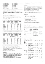
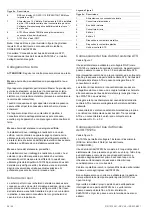
Table 6: RAS address and reader function
IN IN OUT
OUT
Door
1
1 5 9 13
Door
2
2 6 10 14
Door
3
3 7 11 15
Door
4
4 8 12 16
Outputs
The four-door DGP has one output available as a switched
power output (external siren output). There are also four on-
board unlock relays available, one for every door (K1 to K4).
A four-door DGP can address 48 outputs in total using macro
logic.
Output controllers are used to expand the number of outputs
on a DGP. Each output controller expands the outputs by
eight. Output and zone numbers are always the same as the
first 16 zone numbers on the DGP to which they are
connected.
Outputs devices
ATS1810:
Four-way relay card allows the use of output
numbers 5 to 8 of the outputs allocated to the DGP address.
For example, DGP 1 uses unlock relays 17 to 20 for opening
doors, and outputs 21 to 24 are available on the relay card.
Note:
This card cannot be used together with
ATS1811/ATS1820 clocked output cards.
ATS1811:
Eight-way relay cards allow use of output numbers
5 to 48 of the outputs allocated to the DGP address. For
example, DGP 1 uses unlock relay 17 to 20 for opening doors,
and outputs 21 to 63 are available on the relay cards.
ATS1820:
16-way open collector card. It is the same as
ATS1811.
The four-door DGP can activate outputs 33 to 63 only by
utilizing macro logic.
When using more than two ATS1811 or ATS1820, use a
separate power supply.
ATS125x default zone and relays settings
Table 7: ATS125x defaults
Door 1 Door 2 Door 3 Door 4
Door
contact
1 3 5 7
Request-to-Exit
zone 2 4 6 8
DOTL
9 10 11 12
Door
relay
K1 K2 K3 K4
The zone numbers in this table refer to the physical zone
numbers on the ATS125x PCB.
The system zone numbers relating to these functions for each
of the ATS125x can be found in Table 5.
Содержание Interlogix ATS125 Series
Страница 56: ...56 56 P N 1070341 REV 2 0 ISS 22FEB11 ...